Mesh Generation Algorithms
- Home
- Blog Details
- February 19 2019
- admin
Mesh is the various aspects upon which a mesh can be classified. Mesh generation requires expertise in the areas of meshing algorithms, geometric design, computational geometry, computational physics, numerical analysis, scientific visualization, and software engineering to create a mesh tool.
FAQs
What is Mesh?
A mesh (also known as meshing) is a network that constitutes of cells and points.
What is Mesh Generation?
Mesh generation is the practice of converting the given set of points into a consistent polygonal model that generates vertices, edges and faces that only meet at shared edges. It can have almost any shape in any size.
What are the primary constituents of a mesh?
A mesh is a collection of vertices, edges and faces that defines the shape of a polyhedral object in 3D graphics and solid modeling. Objects created with meshes must have the following elements:
- Vertex
- Edge
- Face
- Surfaces
Over the years, mesh generation technology has evolved shoulder to shoulder with increasing hardware capability. Even with fully automatic mesh generators, there are many cases where the solution time is less than the meshing time. Meshing can be used for a wide array of applications; however, the principal application of interest is the finite element method. Surface domains are divided into triangular or quadrilateral elements, while volume domain is divided mainly into tetrahedral or hexahedral elements. A meshing algorithm can ideally define the shape and distribution of the elements.
A vital step of the finite element method for numerical computation is mesh generation algorithms. A given domain is to be partitioned into simpler ‘elements.’ There should be a few elements, but some domain portions may need small elements to make the computation more accurate. All elements should be ‘well-shaped.’ Let us walk through different meshing algorithms based on two common domains: quadrilateral/hexahedral mesh and triangle/tetrahedral mesh.
Algorithm methods for Quadrilateral or Hexahedral Mesh
Grid-Based Method
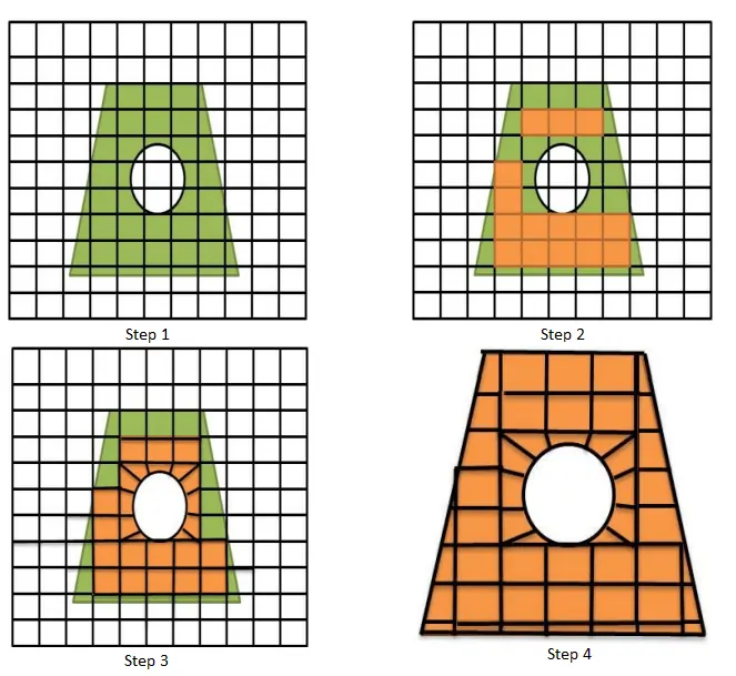
The grid-based method involves the following steps:
- A user-defined grid is affixed to a 2D & 3D object. It generates quad/ hex elements on the interior of the object.
- Some patterns are defined for boundary elements, followed by forming a boundary element by applying a boundary intersection grid.
- It results in the generation of a quadrilateral mesh model.
Medial Axis Method
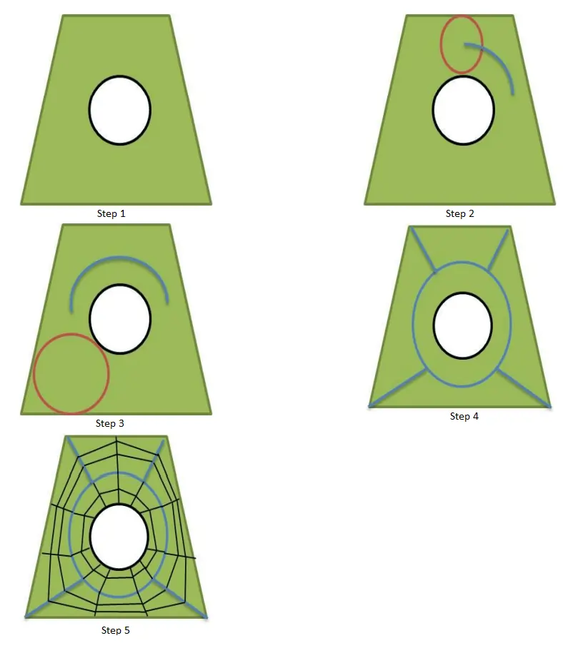
The medial axis method involves an initial decomposition of the volumes. The technique involves a few steps as given below:
- Consider a 2D object with a hole.
- A maximal circle is rolled through the model, and the circle’s center traces the medial object.
- The medial object is used to decompose the model into a simple meshable region automatically.
- The medial axis method forms a series of templates for the region to fill the area with quad elements.
Plastering method
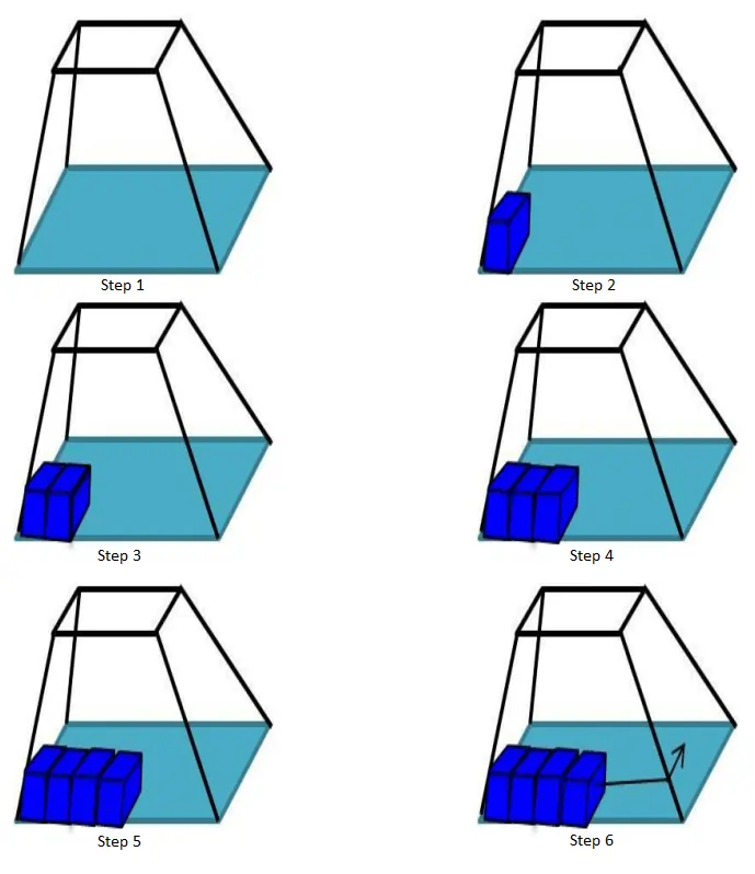
Plastering is the process in which elements are placed, starting with the boundaries and advancing towards the center of the volume. The steps of this method are as follows:
- A 3D object is taken.
- One hexahedral element is placed at the boundary.
- Individual hexahedral elements are projected towards the interior of the volume to form hexahedral meshing, row by row and element by element.
- The process is repeated until mesh generation is completed.
Whisker Weaving Method
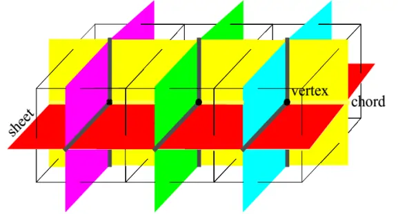
Whisker weaving is based on the spatial twist continuum (STC) concept. The STC is the dual of the hexahedral mesh, represented by an arrangement of intersecting surfaces that bisects hexahedral elements in each direction. The whisker weaving algorithm can be explained in the following steps:
- The first step is constructing the hex mesh’s STC or dual.
- The hex elements can be fitted into the volume using the STC as a guide with a complete STC. The loops can be easily determined from an initial quad mesh of the surface.
- Hexes are formed inside the volume once a valid topological representation of the twist planes is achieved. One hex is formed wherever three twist planes converge.
Paving Method
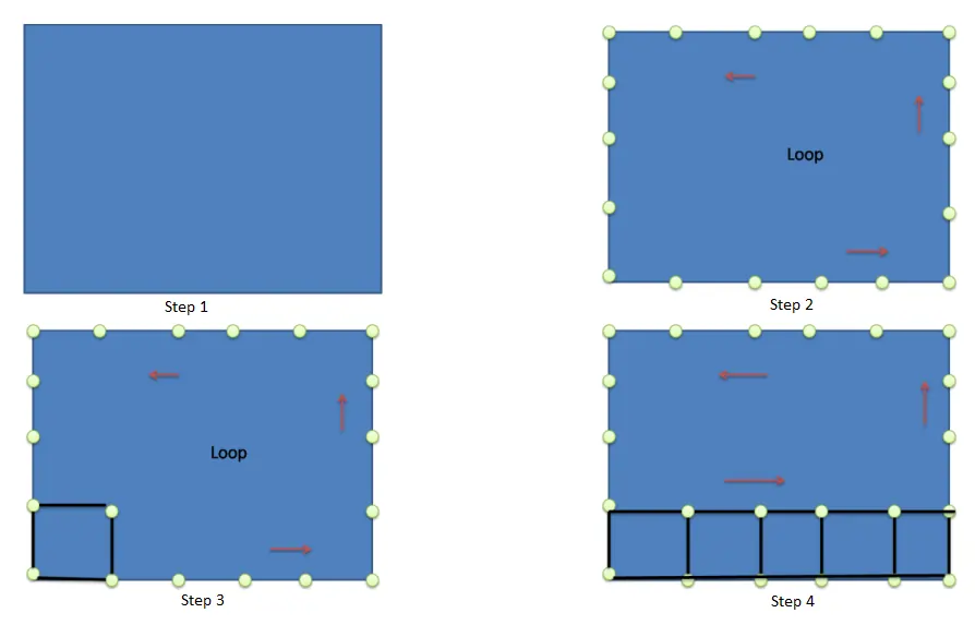
The paving method has the following steps to generate a quadrilateral mesh:
- Initially, a 2D object is taken.
- A node is inserted in the boundary, and the boundary node is considered a loop.
- A quadrilateral element is inserted, and a row of elements is formed.
- The row of the element is placed around the boundary nodes.
- Again this same procedure adopts for the next rows.
- Finally, a quad mesh model is formed.
Mapping Mesh Method
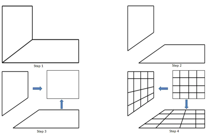
The Mapped method for quad mesh generation involves the following steps:
- A 2D object is taken.
- The 2D object is split into two parts.
- Each part is either a simple 2D rectangular or a square object.
- The simple shape object is unit meshed.
- The unit meshed simple shape object is mapped in its original form and then joined back to form the actual object.
Algorithm methods for Triangular and Tetrahedral Mesh
Quadtree Mesh Method
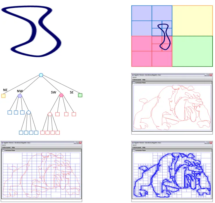
The quadtree mesh method recursively subdivided a square containing the geometric model until the desired resolution is reached. The steps for two-dimensional quadtree decomposition of a model are as follows:
- A 2D object is taken.
- The 2D object is divided into rectangular parts.
- A Detail tree of a divided object is provided.
- The object is eventually converted into a triangle mesh.
Delaunay Triangulation Method
A Delaunay triangulation for a set P of discrete points in the plane is a triangulation DT such that no points in P are inside the circum-circle of any triangles in DT. The steps of construction Delaunay triangulation are as follows:
- The first step is to consider some coordinate points or nodes in space.
- The condition of a valid or invalid triangle is tested every three points, which finds some right triangle to make a triangular element.
- Finally, a triangular mesh model is obtained.
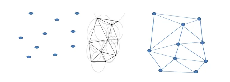
Delaunay Triangulation maximizes the minimum angle of all the triangle angles and tends to avoid skinny triangles.
Advancing Front Method
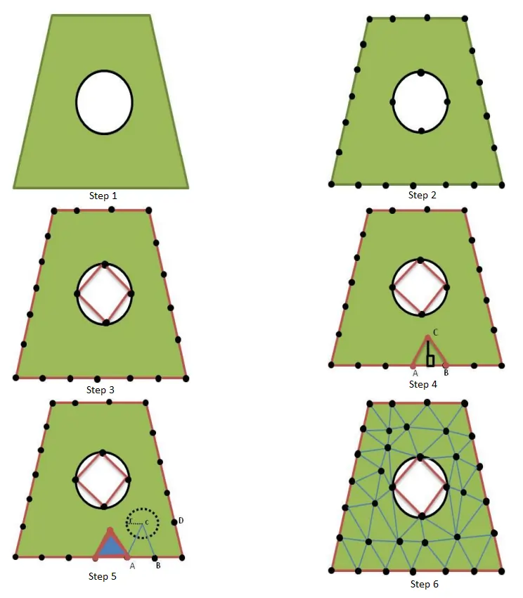
Another famous family of triangular and tetrahedral mesh generation algorithms is the advancing front or moving front method. The mesh generation process is explained in the following steps:
- A 2D object with a hole is taken.
- An inner and outer boundary node is inserted. The user determines the node spacing.
- An edge is inserted to connect the nodes.
- To start the meshing process, an edge AB is selected. A perpendicular edge is drawn from the AB’s midpoint to point C (where the user determines the user’s node spacing) to make a triangular element.
- After generating one element, another edge is selected as AB, and a point C is made. Still, if in case any other node lets point D within the defined radius, then the ABC element is canceled, and instead, an element ABD is formed.
- This process is repeated until mesh is generated.
Spatial Decomposition Method
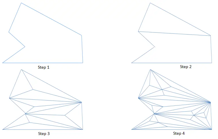
The steps for the spatial decomposition method are as follows:
- Initially, a 2D object is taken.
- The 2D object is divided into minute parts till we get the refined triangular mesh.
Sphere Packing Method
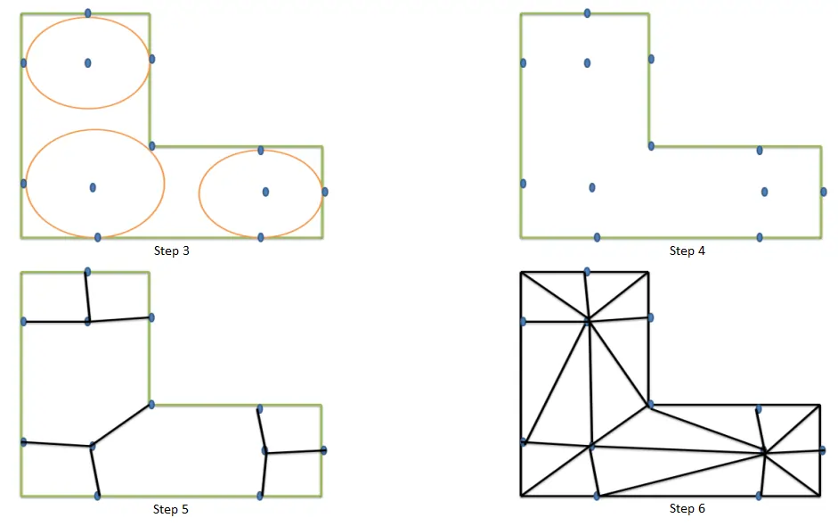
The sphere packing method follows the given steps:
- Before constructing a mesh, the domain is filled with circles.
- The circles are packed together so that three or four tangent circles surround the gaps between them.
- These circles are then used as a framework to construct the mesh by placing mesh vertices at circle centers, points of tangency, and within each gap while using generated points. Eventually, the triangular mesh is generated.
Get access to our mesh tools library today
Mesh Tools library offers a comprehensive set of operation for meshes for all your needs. Developed in C++, this library can be easily integrated in to your product. To learn more,

