What is CAD | Types of CAD Models and CAD Formats
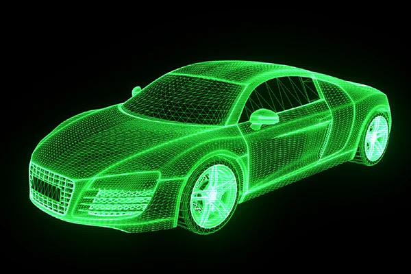
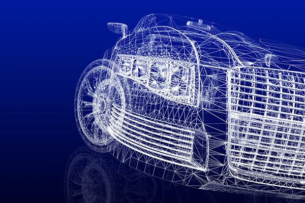
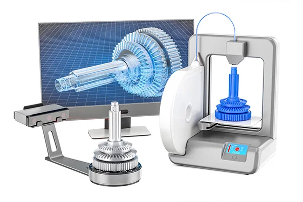
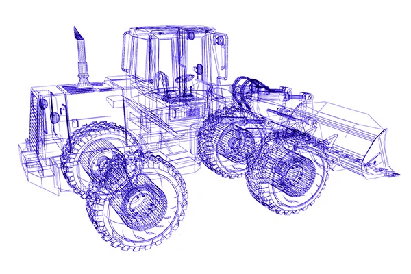
Table of content What is CAD? Types of CAD models Types of CAD formats Use of CAD What is CAD? Computer-Aided Design, aka CAD, is undoubtedly a crucial stage in product development. By definition, CAD is the acronym for Computer-Aided Design. It covers various design tools used by multiple professionals like artists, game designers, manufacturers, and design engineers. After a meshed part is aligned, it goes through surface modeling in tools such as Polyworks. It generates a non-parametric model (IGES or STEP format) or parametric modeling where a sketch of the meshed part is created instead of putting it through surfacing (.PRT format). The resultant is generally called a 3D computer-aided model or CAD model. The technology of CAD systems has tremendously helped users by performing thousands of complex geometrical calculations in the background without anyone dropping a sweat for it. CAD has its origin in early 2D drawings where one could draw objects using basic views: top, bottom, left, right, front, back, and the angled isometric view. 3D CAD programs allow users to take 2D pictures and convert them into a 3D object on the screen. In a simple definition, CAD design is converting primary design data into a more perceptible and more understandable design. Each CAD system has its algorithm for describing geometry mathematically and structurally. Types of CAD models. Everything comes with its variety, and CAD modeling is no stranger. As the technology evolved, CAD modeling came up in different styles. There are many methods of classifying them, but a broad general classification can be as follows: Two-dimensional or 2D CAD: The early version of CAD that most of us are aware of. These are 2-dimensional drawings on a flat sheet with dimensions, layouts, and other information needed to manufacture the object. The 2D CAD objects consist of lines, ovals, circles, ovals, curves, and slots. 2D CAD platforms generally come with a library of geometric images and the ability to create Bezier curves, polylines, and splines. They are also capable of generating a bill of materials (BOM). 2.5D CAD:The 2.5 D CAD are prismatic, which means they represent the depth of an object. They fall between 2D and 3D CAD, and the objects consist of geometric patterns like in 2D CAD. Three-dimensional or 3D CAD:The purpose of both 2D and 3D models is the same. But what sets 3D models apart is their ability to present more excellent details about the individual component and assembly by projecting it as a full-scale 3-dimensional object. 3D CAD offers a realistic portrayal of the CAD model. 3D models can be viewed and rotated in X, Y, or Z axes. It also shows how two objects can fit and operate, which is impossible with 2D CAD. 3D models can be further classified into three categories: 3D Wire-frame Models:These models resemble an entire object made of just wires, with the background visible through the skeletal structure. Surface Models:Surface models are the next stage of wireframe models, and they are created by joining the 3D surfaces together and look like real-life objects. Solid Models:They best represent real physical objects in a virtual environment. Unlike other models, solid models have weight, volume, and density properties. They are the most used models and serve as prototypes for engineering projects. The Boundary Representation (BREP) solid modeling links Constructive Solid Geometry (CSG) images while a hybrid systems mix CSG and BREP to attain the intended design. Types of CAD formats Different professionals use different software platforms for various reasons like cost, project requirements, features, etc. Although the software comes with its file formats, there are instances where one needs to share their project with someone else, either partners or clients, who are using different software. In such cases, it is necessary that both parties’ software understand each other’s file formats or, in other words, interoperable. As a result of this situation, it is essential to have file formats that can be accommodated in various software. CAD file formats can be broadly classified into two types: STEP: This is the most popular CAD file format of all. It is widely used and highly recommended as most software support STEP files. STEP is the acronym for Standard for the Exchange of Product Data. IGES: IGES is the acronym for Initial Graphics Exchange Specification. It is an old CAD file format that is vendor-neutral. IGES has fallen out lately since it lacks many features that newer file formats have. Parasolid: Parasolid was initially developed by Shape Data and is currently owned by Siemens PLM Software. STL: STL stands for Stereolithography which is the format for 3D information created by 3D systems. STL finds its usage mostly in 3D printers. STL describes only the outer structure or surface geometry of a physical object but doesn’t give out the color, texture, and other attributes of an object. VRML: VRML stands for Virtual Reality Modeling Language. Although it gives back more attributes than STL, a handful of software can read it. Prototyping & pilot runs (preliminary design stage) In this stage, prototypes are built and tested after several iterations, and a pilot run of the manufacturing process is conducted. This stage involves creating rapid prototypes for a concept deemed to have business relevance and value. Prototype means a ‘quick and dirty’ model rather than a refined one that will be tested and marketed later. Adjustments are carried out as required before finalizing the design. X3D: X3D is an XML-based file format for representing 3D computer graphics. COLLADA: COLLADA stands for Collaborative Design Activity and is mostly used in gaming and 3D modeling. DXF: DXF stands for Drawing Exchange Format, a pure 2D file format native to AutoCAD. Use of CAD CAD technology has placed the entire engineering process in an adrenaline mode. It is possible to mold or fold, modify, or make a new part from scratch, all with the help of CAD modeling software. The many uses of CAD are as follows:CAD generates design and layouts, details and calculations, and 3-D
Read MoreMesh – List of operations
Good cell quality of meshes translate into accurate results within optimum time after computation. But more often than not, we get a mesh output, which is far from accuracy. There are number of factors affecting a mesh, that might compromise with the final result. This chapter focuses on the various shortcomings of a mesh and their repair algorithms. Mesh Decimation/Simplification Mesh decimation/simplification is the method of reducing the number of elements used in a mesh while maintaining the overall shape, volume and boundaries preserved as much as possible. It is a type of algorithm that aims to transform a given mesh into another with fewer elements (faces, edges and vertices). The decimation process usually involves a set of user-defined quality criteria, that maintains specific properties of the original mesh as much as possible. This process reduces the complexity of a mesh. Mesh Hole-Filling To analyze a mesh model, it must be complete. Often, some mesh models carry holes in them, which must be filled. The unseen areas of the model appear as holes, which are aesthetically unsatisfying and can be a hindrance to algorithms that expect a continues mesh. The Fill Hole command fills the holes and gaps in the mesh. Note – The Fill Hole command only works on triangulated mesh and not tetrahedral mesh Mesh Refinement Certain situations arise which makes us concerned about the accuracy a model in certain areas. Such scenarios prompt us to have fine mesh in those areas to ensure accurate results. However, creating a surface mesh of the entire model with a fine mesh size may ask for unnecessary hours to analyze the fine mesh in those regions where the results are not as important to you. The answer to this issue is the usage of refinement points. A refinement point identifies a region or volume of space in which a finer mesh has to be generated. Mesh refinement can be defined by identifying an absolute size for the local mesh. Mesh refinement ends up in creating more number of elements in the specified region of the model. Mesh Smoothing Mesh smoothing is also known as mesh relaxation. Sometimes it is necessary to modify that mesh after a mesh generation. It is achieved either by changing the positions of the nodes or by removing the mesh altogether. Mesh smoothing results in the modification of mesh point positions, while the topology remains as it is.
Read MoreMesh Generation Algorithms
Table of content FAQs Algorithm methods for Quadrilateral or Hexahedral Mesh Algorithm methods for Triangular and Tetrahedral Mesh Mesh is the various aspects upon which a mesh can be classified. Mesh generation requires expertise in the areas of meshing algorithms, geometric design, computational geometry, computational physics, numerical analysis, scientific visualization, and software engineering to create a mesh tool. FAQs Over the years, mesh generation technology has evolved shoulder to shoulder with increasing hardware capability. Even with fully automatic mesh generators, there are many cases where the solution time is less than the meshing time. Meshing can be used for a wide array of applications; however, the principal application of interest is the finite element method. Surface domains are divided into triangular or quadrilateral elements, while volume domain is divided mainly into tetrahedral or hexahedral elements. A meshing algorithm can ideally define the shape and distribution of the elements. A vital step of the finite element method for numerical computation is mesh generation algorithms. A given domain is to be partitioned into simpler ‘elements.’ There should be a few elements, but some domain portions may need small elements to make the computation more accurate. All elements should be ‘well-shaped.’ Let us walk through different meshing algorithms based on two common domains: quadrilateral/hexahedral mesh and triangle/tetrahedral mesh. Algorithm methods for Quadrilateral or Hexahedral Mesh Grid-Based MethodThe grid-based method involves the following steps: Medial Axis MethodThe medial axis method involves an initial decomposition of the volumes. The technique involves a few steps as given below: Plastering methodPlastering is the process in which elements are placed, starting with the boundaries and advancing towards the center of the volume. The steps of this method are as follows: Whisker Weaving MethodWhisker weaving is based on the spatial twist continuum (STC) concept. The STC is the dual of the hexahedral mesh, represented by an arrangement of intersecting surfaces that bisects hexahedral elements in each direction. The whisker weaving algorithm can be explained in the following steps: Paving MethodThe paving method has the following steps to generate a quadrilateral mesh: Mapping Mesh MethodThe Mapped method for quad mesh generation involves the following steps: Algorithm methods for Triangular and Tetrahedral MeshQuadtree Mesh MethodThe quadtree mesh method recursively subdivided a square containing the geometric model until the desired resolution is reached. The steps for two-dimensional quadtree decomposition of a model are as follows: Delaunay Triangulation MethodA Delaunay triangulation for a set P of discrete points in the plane is a triangulation DT such that no points in P are inside the circum-circle of any triangles in DT. The steps of construction Delaunay triangulation are as follows: Delaunay Triangulation maximizes the minimum angle of all the triangle angles and tends to avoid skinny triangles. Advancing Front MethodAnother famous family of triangular and tetrahedral mesh generation algorithms is the advancing front or moving front method. The mesh generation process is explained in the following steps: Spatial Decomposition MethodThe steps for the spatial decomposition method are as follows: Sphere Packing MethodThe sphere packing method follows the given steps: Get access to our mesh tools library today Mesh Tools library offers a comprehensive set of operation for meshes for all your needs. Developed in C++, this library can be easily integrated in to your product. To learn more,
Read MoreMesh Quality
The quality of a mesh plays a significant role in the accuracy and stability of the numerical computation. Regardless of the type of mesh used in your domain, checking the quality of your mesh is a must. The ‘good meshes’ are the ones that produce results with fairly acceptable level of accuracy, considering that all other inputs to the model are accurate. While evaluating whether the quality of the mesh is sufficient for the problem under modeling, it is important to consider attributes such as mesh element distribution, cell shape, smoothness, and flow-field dependency. Element Distribution It is known that meshes are made of elements (vertices, edges and faces). The extent, to which the noticeable features such as shear layers, separated regions, shock waves, boundary layers, and mixing zones are resolved, relies on the density and distribution of mesh elements. In certain cases, critical regions with poor resolution can dramatically affect results. For example, the prediction of separation due to an adverse pressure gradient depends heavily on the resolution of the boundary layer upstream of the point of separation. Cell Quality The quality of a cell has a crucial impact on the accuracy of the entire mesh. The quality of cell is analyzed by the virtue of three aspects: Orthogonal quality, Aspect ratio and Skewness. Orthogonal Quality: An important indicator of mesh quality is an entity referred to as the orthogonal quality. The worst cells will have an orthogonal quality close to 0 and the best cells will have an orthogonal quality closer to 1. Aspect Ratio: Aspect ratio is an important indicator of mesh quality. It is a measure of stretching of the cell. It is computed as the ratio of the maximum value to the minimum value of any of the following distances: the normal distances between the cell centroid and face centroids and the distances between the cell centroid and nodes. Skewness: Skewness can be defined as the difference between the shape of the cell and the shape of an equilateral cell of equivalent volume. Highly skewed cells can decrease accuracy and destabilize the solution. Smoothness Smoothness redirects to truncation error which is the difference between the partial derivatives in the equations and their discrete approximations. Rapid changes in cell volume between adjacent cells results in larger truncation errors. Smoothness can be improved by refining the mesh based on the change in cell volume or the gradient of cell volume. Flow-Field Dependency The entire effects of resolution, smoothness, and cell shape on the accuracy and stability of the solution process is dependent upon the flow field being simulated. For example, skewed cells can be acceptable in benign flow regions, but they can be very damaging in regions with strong flow gradients. Correct Mesh Size Mesh size stands out as one of the most common problems to an equation. The bigger elements yield bad results. On the other hand, smaller elements make computing so long that it takes a long amount of time to get any result. One might never really know where exactly is the mesh size is on the scale. It is important to consider chosen analysis for different mesh sizes. As smaller mesh means a significant amount of computing time, it is important to strike a balance between computing time and accuracy. Too coarse mesh leads to erroneous results. In places where big deformations/stresses/instabilities take place, reducing element sizes allow for greatly increased accuracy without great expense in computing time.
Read MoreReverse Engineering: Outsourcing and Beyond
FAQs Points to keep in mind while outsourcing reverse engineering services Choosing a Vendor all know reverse engineering is an economical approach towards product development & innovation, which manufacturers often utilize to evaluate and redesign competitor products. Reverse Engineering services involve understanding the product design, system integrity, and manufacturing processes involved to realize the potential required to build a similar or improved product version. The reverse engineering technique is best suitable for producing design data and related technical manuals for products that no longer have any design information. The entire work process involves engineers studying every design feature, associated manufacturing processes, and tools needed for product development and storing information. After digitizing the complete information, suitable design modifications are carried out as per requirements. However, to get things right, one should have an efficient and dedicated engineering team, the right software, hardware tools, etc., which seems difficult to have within the organization. FAQs Here comes the advantage of outsourcing reverse engineering projects where the activities can significantly reduce the cost of product development and burden the engineers who can focus on developing innovative design solutions for the product.Reverse engineering services outsourcing might invoke some hesitancy. To address it, here are some of the crucial benefits of outsourcing reverse engineering projects: Still have more questions, ask us Prescient Technology’s reverse engineering expertise has helped companies meet their designing and innovative demands. If you wish to know more, just click the button below. Points to keep in mind while outsourcing reverse engineering services As feasible as reverse engineering outsourcing sounds, there are specific steps to follow and factors to consider. Few crucial points to discuss when outsourcing reverse engineering services are as follows: Choosing a Vendor After finalizing the decision to outsource reverse engineering service, the next vital step to consider is choosing a vendor. A responsive and efficient vendor makes all the difference. Finding a professional vendor with a high level of efficiency and even heightened work ethic is a complex but satisfying process. Be aware that once you are engaged with a vendor, it becomes a little difficult to break the deal and discontinue ‘business’ with the existing vendor. So choose carefully but commit completely after the contract.When a vendor has been finalized, the organization issues a request for quotation (RFQ). RFQs are created to invite suppliers to a bidding process to bid on specific services/products. The organization should also take a legal approach and have the service provider’s non-disclosure agreement (NDA). This is done to prevent unlawful, authorized distribution, or illicit product adoption.Now that the legal approach and paperwork have been taken care of, the organization sends the physical product to the service provider or the scanned files, depending on the company’s needs. The vendor is also supplied with measurement specifications and related industry standards to follow. Eventually, the vendor creates a digital format and sends it back to the organization for further design modification or innovation investigations.For manufacturers, reverse engineering is a profitable strategy in today’s competitive scenario; however, outsourcing brings along the other benefits that ensure the product development process remains cost-effective. Prescient Technologies is adept at providing outstanding reverse engineering services and has extensive experience in the end-to-end process, so feel free to contact us today.
Read MoreFuture of Reverse Engineering
Reverse engineering found its use in various industries gradually, as more and more industry leaders adopted this approach and implemented the same, thereby easing out their own work-process. Here is a list of industries that use reverse engineering as a part of their methods: The future It is the 21st century. These are great times for design engineers. Over the past two decades, their job has been dramatically changed, with the transformation of finite element analysis (FEA) software from mainframe to desktop computer. With the easy availability of computer-aided design software packages, reverse engineering technology has become a practical means to create a 3D virtual model of an existing physical part. That, in turn, has made the use of 3D CAD, CAM, or other CAE applications easier. The convenience in the usage, affordability and the ability of its software to tightly integrate with a CAD program has made this process a much favored among engineers. At the same time, the costs of scanners and other hardware used to input measurements have been dropping, and the hardware is becoming smaller and easier to use, according to the hardware makers.
Read MoreReverse Engineering Inspection and its use
The quality control and inspection process in reverse engineering usually take three steps to determine if the 3D CAD model of the part is available or not. Those three steps are as follows: Following are some uses of Reverse engineering inspection:
Read MoreWhat are Parametric and Non-parametric Modeling
Table of content Parametric Model/Modeling Non-parametric Model/Modeling In the past, designers resorted to the physical measurement of the product to redraw its geometry. Today, designers use 3D scanners to capture measurements. The scanned data is then imported to CAD, where the design can be analyzed, processed, manipulated, and refined. Two key aspects that fall in place when focusing on the reverse engineering process are: Parametric Model/Modeling A parametric model captures all its information about the data within its parameters. All you need to know to predict a future data value from the model’s current state is its parameters. The parameters are usually finite in dimensions. Knowing the parameters for a parametric model to predict new data is enough. A parametric model is one where we assume the ‘shape’ of the data and, therefore, only have to estimate the coefficients of the model. A significant advantage of parametric modeling is that it compactly describes the underlying process, making further data processing more accessible. However, most work in parametric system identification relies on the assumption of time-invariance of the system and stationarity of the observed signal. But this assumption is not valid for all signals. In these cases, a heuristic approach often determines the optimal reduced model. Parametric models keep a history of the parameters that determine a model’s geometry. As a result, they allow the user to explore different design options while minimizing edit time. Similarly, parametric models can be visualized in 3D drawing programs. It means that they can more closely simulate the actual behavior of the original project. Non-parametric Model/Modeling A non-parametric model can capture more subtle aspects of the data. It allows more information to pass from the current set of data attached to the model at the current state to predict future data. The parameters are usually said to be infinite in dimensions. Hence, it can express the characteristics in the data much better than parametric models. For a non-parametric model, predicting future data is based not just on the parameters but also on the observed data state. A non-parametric model is one where we do not assume the ‘shape’ of the data, and we have to estimate the most suitable form of the model, along with the coefficients. Parametric models require a fixed number of parameters, while non-parametric ones don’t. The former is better for models with well-defined and predictable input data. Non-parametric models can be trained with a more significant number of data. However, the disadvantages of a parametric model are greater training time. While both models effectively predict the future, the latter tends to produce better results. The former requires less training data but is faster than non-parametric methods. Non-parametric models have the disadvantage of overfitting because they need many observations to approximate f. Non-parametric models have a much lower precision rate but can produce better-fitting models. As for the disadvantages of both models, parametric models are generally easier to understand and use. Besides requiring less training data, parametric models tend to produce poorer results. It is why they are more popular. However, the benefits of non-parametric algorithms are far outweighed by their disadvantages. The latter is often better for data that are not linear or have many missing values. Parametric models use different methods to estimate model parameters. Parametric modeling is based on mathematical functions, while non-parametric models are based on data. The difference between the two is a big one and can make the difference between success and failure in the field of statistics.
Read MoreThe Reverse Engineering process
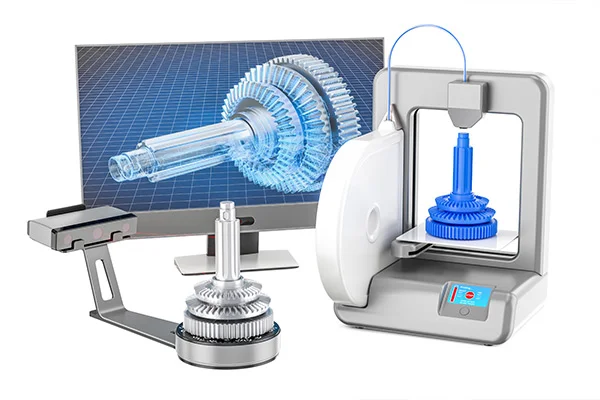
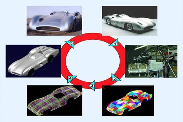
Sometimes, situations arise where you don’t have access to a part’s original design documentation from its original production. This might be due to the absence of the original manufacturer altogether or stoppage on the production itself. Reverse engineering empowers us to analyze a physical part and explore how it was originally built to replicate, create variations, or improve on the design. The goal is to ultimately create a new CAD model for use in manufacturing. Let us take a look at the steps involved in reverse engineering. Commonly, it involves careful executions of the following steps: Scanning The first step involves using a 3D scanner for collecting the geometric measurements and dimensions of the existing part quickly and accurately using projected light patterns and camera system. Generally, the types of scanners used for such execution are blue light scanner, white light scanner, CT scanner and /or laser scanner. The former two captures the outward dimension and measurements while the latter two is capable of scanning the entire inside out. Point Cloud Once a certain part is scanned, the data gets transformed in the form of point clouds. Point cloud is a 3D visualization consisting of thousands or even millions of points. Point clouds define the shape of a physical system. Meshing/Triangulation This stage serves involves conversion of point clouds to mesh (STL or Stereolithographic format). Mesh generation is the practice of converting the given set of points into a consistent polygonal model that generates vertices, edges and faces that only meet at shared edges. Common software tools used to merge point clouds are Polywords, Geomatics, Image Ware, MeshLab. The meshed part is then run for alignment in the mentioned software tools. Parametric/Non-parametric Modeling After the meshed part is aligned, it goes through either of two stages. The first option involves applying surface modeling on meshed part in tools such as Polyworks. It results in the generation of non-parametric model (IGES or STEP format). An alternate option is creating a sketch of the meshed part instead of putting it through surfacing. This work-process is known as parametric modeling (.PRT format). For a non parametric model, predicting future data is based on not just the parameters but also in the current state of data that has been observed. For a parametric model to predict new data, knowing just the parameters is enough. CAD Modeling The next stage consists of transferring the data through CAD software tools such as NX, Catia, Solidworks, Cero etc., for applying functions such as ‘stitch’, ‘sew’, ‘knit’, ‘trim’, ‘extrude’, ‘revolve’ etc for creation of 3D CAD model. Inspection This stage includes visual computer model inspections and alignment of the merged models against actual scanned parts (STL) for any discrepancies in the geometry as well as dimensions. Generally, inspection is carried out by using tools such as Polyworks or Geomagic. Reverse engineering inspection provides sufficient information to check tolerances, dimensions and other information relevant to the project. Documentation Documentation of 3D stage model depends solely on one’s technical/business requirements. This step is about converting 3D model to 2D sketch, usually with the help of tools such as inventor or Isidra/Coral draw, citing measurements which can be used for reference in the future.
Read MoreWhat is Reverse Engineering ?
Let us start with an example. One day you get into your garage and find on the workbench a ‘black box’. Stricken by curiosity, you build up an urge to discover what it ‘is’ and what it ‘does’. You start with an inspection of the box’s dimensions, color. Then you try to find its purpose and then how it operates. Not satisfied, you try to open it, break it apart, piece by piece in an attempt to understand what each component does and build up a pattern of how they would all interact together as one system. Finally you reach the end of your inquisition. You now fully (or partially) understand the box. This very approach is termed as Reverse Engineering.Reverse engineering, also known as back engineering, is the process where a man-made object is dismantled completely to reveal its architecture, design or to extract knowledge from the object about its functioning and structural integrity. Why do you need Reverse Engineering? There might be innumerable reasons to adopt reverse engineering process. Some of the common cases are as follows:
Read More