The Advantages And Limitations Of Additive Manufacturing: A Comprehensive Overview
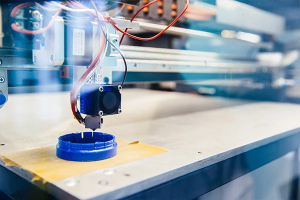
Table of content Top 6 Advantages of Additive Manufacturing: Top 6 Limitations of Additive Manufacturing Conclusion In the last few years, 3D printing and additive manufacturing have enhanced the scope of production. 3D printing is the process of putting layers of material together to make things that are three-dimensional. This technology is better than the old ways of making things in a lot of ways, but it comes with its own set of limitations. Here, we’ll look more closely at the top six pros and cons of additive manufacturing. Top 6 Advantages of Additive Manufacturing: 1.Reduced Time and Cost One benefit of additive manufacturing is that it makes production faster and cheaper. Usually, when making a new product, you start by making a prototype, then the tools, and finally the finished product. This process could take a long time and cost a lot of money. But additive manufacturing makes the process go faster. 2.Complex Geometries With additive printing, you can make things that would be hard to make in any other way. Additive manufacturing can be used to make structures with hollow channels inside and curved surfaces.3 3.Customization and Personalization Additive manufacturing makes it possible to change and personalize products. In traditional manufacturing, the same product is made over and over again, and there is no way to change it. Customers can use additive manufacturing to make one-of-a-kind items with their own specs, sizes, and shapes. 4.Reduced Material Waste If additive manufacturing is used, there may be less need to throw away materials. With traditional ways of making things, like subtractive manufacturing, a lot of materials are wasted. In additive manufacturing, just the right amount of material is used. This cuts down on waste and saves money on materials. 5.Faster Prototyping One more benefit of additive manufacturing is that prototyping can be done more quickly. When standard production methods are used, prototyping can take a long time and cost a lot of money. Additive manufacturing can be used to make prototypes quickly and cheaply. You can easily change designs, try out new materials and shapes, and repeat the process. This makes it easier and cheaper to get products to market faster. 6.Simplified Supply Chains Since additive manufacturing makes it possible to make things only when they are needed, supply chains may be easier to run. Instead of making a lot of the same thing and storing it in warehouses, additive manufacturing lets people make things as they need them. This might make people need less storage space and be less likely to keep things they don’t need. Top 6 Limitations of Additive Manufacturing: 1.Limited Materials One problem with additive manufacturing is that it can only print with a certain number of materials at one time. Even though the number of materials is growing, it is still very small compared to conventional methods. This limitation could affect how well the final product works, how long it lasts, and how well it lasts. 2.Surface Quality A glaring limitation of additive manufacturing is that the surface quality of the parts is still not very good. Especially, when complex structures are made, a smooth surface finish is difficult to achieve. 3.Size Limitations With additive manufacturing, the size of objects may be limited. How big an item is depends on how big the printer is and how much room it has to work with. Larger things may need to be printed in parts before they can be put together. This will take time and make the process harder. 4.Complexity Limitations Using additive manufacturing, you can make buildings with complex shapes, but the shapes can only be complicated. Complex designs can be hard to make because they often need more support structures or post-processing steps, which take more time and money. 5.Limited Scale Another problem with additive manufacturing is that it can only make small quantities. Additive manufacturing is great for making small batches of goods, but it’s not ready yet to make a lot of things at once. This is because additive manufacturing is a slow method that might take a long time to make a lot of parts. 6.Environmental Impact When you use additive printing, it might be hard to get rid of things like support structures and failed prints. Also, if the materials used in additive manufacturing are not recycled or thrown away in the right way, they could hurt the environment. Conclusion In conclusion, additive manufacturing is faster, cheaper, more flexible, and wastes less material. It does, however, have a number of flaws, including a paucity of materials, poor surface quality, small size, and complexity issues. Despite these problems, additive manufacturing is an important part of the manufacturing industry and will continue to change and improve over time. Do you want to go to the next level with additive manufacturing? We can help you at Prescient Technologies. Our software development services could change the way you think about 3D printing and other methods of “additive manufacturing.” References:
Read MoreAdditive Manufacturing: The past and the prominence of 3D Printing
Additive Manufacturing is one of the most significant reforms in a fast-changing world of manufacturing and construction. Additive manufacturing has triggered newer processes, sustainable output, smart machines, and more unique means of operation, management, and increased efficiency. Additive manufacturing is a computer-operated and controlled system that creates three-dimensional objects by carefully sequentially depositing various material compositions in layers. A comprehensive digital layout is fed as design data, and the machine operates accordingly. Additive manufacturing is mainly used for making rapid prototypes and forging complex geometric objects. The other names for Additive Manufacturing are 3D printing, Additive Layer Manufacturing. The technology has gained worldwide prominence with the name of 3D printing. FAQ Commercialization of 3D printers 3D printing is not an archaic process, but rather, it came up in the ’80s. Here is a summary of the history of 3D printers in the last four decades: The 80’s witnessed the first commercial use of additive manufacturing with stereolithography from 3D Systems. The SLA-1 was the first commercially released AM machine. Acrylate resins were commercialized. The Somos stereolithography machine also entered the market in the same year. In the ’90s, Germany’s Electro-Optical Systems sells the first stereolithography system. Fused deposition modeling (FDM), solid ground curing (SGC), and laminated object manufacturing (LOM) were commercialized. Selective laser sintering (SLS) and Soliform stereolithography system were also commercialized. This year saw a bunch of new additives manufacturing systems such as ModelMaker, Solid Center, or EOSINT. An inkjet printing mechanism that deposited wax materials layer by layer was also introduced. The late 2000s saw a rapid growth of the 3D printing machine market. The 3D printing Industry witnessed massive investment 2000’s saw the emergence of new technologies. The world got its first commercially available multi-color 3D printer. The Electron Beam melting machine was one of the groundbreaking 3D printing machines introduced in the early 2000s. In March 2015, Exerial was introduced, a large machine with multiple stations to enable continuous production. Early 3D printers were not very light and convenient to handle. Only after the advent of the 21st century have they become more affordable, straightforward, easy to operate, and versatile enough to be used in a wide range of operations ranging from tools & component manufacture, electronics, metalwork, polymers, etc., product prototypes. Past three years, there has been a tendency to employ 3D printing and AM tech in the real estate industry. Current 3D Printing market trends The worldwide 3D printing products and services market valued at around 12.6 billion U.S. dollars in 2020. The industry is expected to grow at a compound annual growth rate of some 17 percent between 2020 and 2023. As more businesses begin to have their printers, printing software will grow faster than printing services. We can see how fast Additive manufacturing emerged within just three decades and how it is relevant across multiple industrial verticals today. Whether it is about building prototypes, constructing affordable housing, or producing components, AM and 3D printing have offered effective systems that triumph over traditional methods. This technology enables faster product development and market entry, smoother product customization, and seamless integration at lesser cost and time. Thus, additive manufacturing provides OEM manufacturers an excellent opportunity to unleash their products at a higher rate at much lesser expenses for great returns and better customer benefits while ensuring sustainability. Reference: 1. Wohlers, T. and Gornet, T., (2016). History of additive manufacturing, Wohlers Report 2016. 2. Global 3D printing products and services market size from 2020 to 2026, Statista
Read MoreValue Engineering
During the lifecycle of a particular product, companies tend to review the existing design to look out for ways to reduce production cost. Even when coming up with a new product, so many manufacturers go for analyzing the same during its design phase so that it requires an optimum level of cost to produce. This is where Value Engineering comes in. Value engineering is an organized method to improve the “value” of a product or service in the lowest of cost. VE is a systematic approach aimed at obtaining the necessary functions in a product, process, or system at the minimum overall cost, thereby maintaining the quality, reliability, performance, and safety. It provides the substitution of materials and methods with less expensive alternatives, without jeopardizing the functionality. It is emphasized totally on the functions of various components and materials, rather than their physical characteristics. Value engineering is also called value analysis. It was Lawrence Miles who came up with the concept of finding substitute materials for parts unavailable. It was found that substitutions not only reduced cost but aided in a better-finished product. It was this new technique that evolved into value engineering today. The value in VE means two components: The function of a product is the specific task it was designed to perform, and the cost refers to the cost of the item during its life cycle. The ratio of function to cost denotes that the value of a product can be increased by either improving its function or decreasing its cost. In value engineering, the cost related to production, design, maintenance, and replacement are included in the analysis. If we take an example of a new tech product which is being designed and is slated to have a life cycle of only two years; the product will be designed with the least expensive materials and resources that will live up to the end of the product’s lifecycle, saving the manufacturer and the end-user money. This is how product value is improved by reducing costs. It is evident that with the increase in function value and decrease in price, the overall product value increases. Stages of Value Engineering There are three main stages to value engineering, which are: Benefits of Value Engineering Value engineering helps an organization in numerous ways: Value engineering concepts apply to business as well as technical situations and consequently lead management to informed, result-oriented decisions. Value engineering has to be treated as a future investment for gaining technology leadership in the industry.
Read MoreDesign Analysis – FEA, CFD, and Mold Flow Analysis
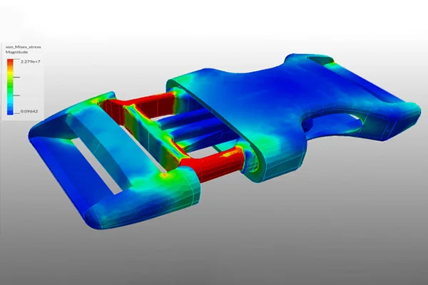
Table of content Finite Element Analysis (FEA) Computational Fluid Dynamics (CFD) Mold Flow Analysis Importance of CAE in design analysis Over the years, the term “Design Analysis” has been essential in the manufacturing sector. Instead of making a prototype and creating elaborate testing regimens to analyze the physical behavior of a product, engineers can evoke this information quickly and accurately on the computer. Design analysis is a specialized computer software technology designed to simulate the physical behavior of an object. If an object will break or deform or how it may react to heat are the sort of queries design analysis can answer. Design analysis helps in minimizing or even eliminating the need to build a physical prototype for testing. As a result, the technology has gone mainstream as a prized product development tool and found its presence in almost all engineering sectors. This article discusses three major design analysis software, namely: Finite Element Analysis (FEA) The Finite Element Analysis (FEA) is a specialized simulation of a physical entity using the numerical algorithm known as the Finite Element Method (FEM). It is used to reduce the number of physical prototypes and experiments and analyze objects in their design stage to develop better products faster. The term ‘finite’ denotes the limited, or finite, number of degrees of freedom used to model the behavior of each element. Mathematics is used to understand and quantify a physical phenomenon such as structural or fluid behavior, wave propagation, thermal transport, the growth of biological cells, etc. Most of these processes are described using Partial Differential Equations. Finite Element Analysis is one of the most prominent numerical techniques for a computer to solve these PEDs. FEA will analyze an object in question by breaking its entire geometry into small ‘elements,’ which are put under simulated conditions to see how the elements react. It displays the results as color- coded 3D images where red denotes an area of failure and blue indicates fields that maintain their integrity under the load applied. However, note down that FEA gives an approximate solution to the problem. FEA is used in problems where an analytical solution is not easily obtained, and mathematical expressions are required because of complex geometries, loadings, and material properties. Engineers also use FEA to reduce the number of physical prototypes, conduct failure investigations and improve component designs. It is also used by forensic engineers to determine stress concentrations in structures and to show alternative designs. Finite element analysis can help analyze fatigue-related failures. Finite element analysis has numerous other applications. Its advantages are many – it enables engineers to make better products faster. By breaking down a complex object into thousands or hundreds of thousands of finite elements, finite element analysis predicts how a given object will respond under a certain load. Furthermore, it helps forensic engineers confirm the stress concentrations in a case and show possible alternatives. FEA is also helpful for fatigue-related failure analysis. Computational Fluid Dynamics (CFD) Computational Fluid Dynamics (CFD) is a specialized simulation that analyzes fluid flows through an object using numerical solution methods. CFD incorporates applied mathematics, physics, and computing software to evaluate how a gas or liquid flows and how it affects an object as it flows past. CFD is based on Navier-Stokes equations which describe how a moving fluid’s velocity, temperature, pressure, and density are related. Aerodynamics and hydrodynamics are two engineering streams where CFD analyses are often used. Physical quantities such as lift and drag or field properties as pressures and velocities are computed using CFD. Fluid dynamics is connected with physical laws in the form of partial differential equations. Engineers transform these laws into algebraical equations and can efficiently solve these equations numerically. The CFD analysis reliability depends on the whole structure of the process. Determining proper numerical methods to develop a pathway through the solution is highly important. The software which conducts the analysis is one of the key elements in generating a sustainable product development process, as the number of physical prototypes can be reduced drastically. CFD is used in almost all industrial domains, such as: With the help of CFD, fluid flow can be analyzed faster in more detail at an earlier stage than by testing, at a lower cost and risk. CFD solves the fundamental equations governing fluid flow processes and provides information on essential flow characteristics such as pressure loss, flow distribution, and mixing rates. CFD injection molding is a widely used manufacturing process for plastic components. It has undergone many improvements over the past few decades, and numerical simulation models enable mold and part design without costly experiments. CFD has become an integral part of the engineering and design domains of prominent companies due to its ability to predict performance of new designs and intends to remain so. Mold Flow Analysis Moldflow, formerly known as C-mould, is one of the leading software used in processwide plastics solutions. Mold flow computes the injection molding process where plastic flows into a mold and analyzes the given mold design to check how the parts react to injection and ensure that the mold will be able to produce the strongest and uniform pieces. Using mold flow analysis, a manufacturer can reduce stress levels in its mold and increase filling and product quality. By assessing the flow of the plastic melt, Mold Flow can make informed design decisions and avoid costly mistakes. This software is an invaluable tool to improve quality and increase productivity. This software is beneficial for manufacturers that need to predict the flow of a mold and determine its feasibility. Two of the most popular mold flow analysis software are Moldflow and Moldex3D, used exclusively by many mold makers. There are three types of Mold flow analysis which are as follows: To simulate mold flow, a network of rectangular elements is discretized on the mold. The corresponding velocity field is then used to calculate the flow of the melt. A two-stage predictor- corrector method, developed by Hieber and Shen, has been used since then. Mold makers typically use the software
Read MoreGeometric Dimensioning and Tolerancing (GD&T)
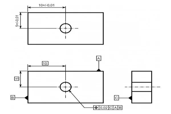
The design model is a depiction of a part design. However, the design model can never be an accurate representation of the product itself. Due to shortcomings in manufacturing and inspection processes, physical parts never match the design model exactly. An essential aspect of a design is to specify the lengths the part features may deviate from their theoretically accurate geometry. It is vital that the design intent and functionality of the part be communicated between the design engineers and the manufacturing unit. It is where the approach of GD&T comes into play. Geometric dimensioning and tolerancing or GD&T is a language of symbols and standards used on engineering drawings and models to determine the allowable deviation of feature geometry. GD&T consists of dimensions, tolerances, definitions, symbols, and rules that enable the design engineers to convey the design models appropriately. The manufacturing unit uses the language to understand the design intent. To master GD&T, one needs to understand the crucial concepts, which includes: GD&T is an efficient way to describe the dimensions and tolerances compared to traditional approximation tolerancing. The engineer might design a part with perfect geometry in CAD, but the produced part, more often than not, turns out to be not accurate. Proper use of GD&T improves quality and reduce time and cost of delivery by providing a common language for expressing design intent.
Read MoreWhat are DFMA and DFMEA
Table of content Design for Manufacturing and Assembly (DFMA) Design Failure Mode and Effect Analysis (DFMEA) During the last few decades, manufacturers have been able to source parts globally with the developments in technology. More and more manufacturers have entered the competition as it grows fierce. Companies in developing nation markets offer products at lower prices. To sustain business and achieve growth, many manufacturers are developing new products to cater to the consumers and widen it. They must be very marketable and of high quality. The Design for Manufacturing and Assembly (DFMA) method enables firms to develop quality products in lesser time and at lower production costs. Design for Manufacturing and Assembly (DFMA) Design for Manufacturing and Assembly or DFMA is a design process that targets ease of manufacturing and assembly efficiency. Simplifying the design of a product makes it possible to manufacture and assemble it in the minimum time and lower cost. DFMA approach has been used in the automotive and industrial sectors mainly. However, the process has been adopted in the construction domain as well. DFMA is a combination of two methodologies which are: DFM and DFA seek to reduce material and labor costs associated with designing and manufacturing a product. For a successful application of DFMA, the two activities should operate in unison to earn the most significant benefit. Through the DFMA approach, a company can prevent, detect, quantify, and eliminate waste and manufacturing inefficiency within a product design. Design Failure Mode and Effect Analysis (DFMEA) Design Failure Mode and Effect Analysis (DFMEA) is a systematic string of activities to identify and analyze potential systems, products, or process failures. Design Failure Mode and Effects Analysis or DFMEA focuses on finding potential design flaws and failures of components before they can significantly impact the end users of a product and the business distributing the product. The design failure mode and effect analysis – DFMEA is an ideal process for any sector where risk reduction and failure prevention are crucial, which includes: With expertise in advanced engineering, Prescient Technologies ensures maximum benefit to their client in terms of value addition, weight reduction, material selection, cost reduction, or manufacturing process selection. Visit our website for more details or send a message.
Read MoreProduct Tear Down Analysis
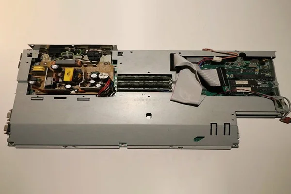
Table of content What is a product teardown? Material Selection Responsibilities of a product teardown team Pre-requisites for a product teardown workshop Length of a product teardown workshop Knowledge and product improvement How do you determine procurement costs for product design, materials, and specifications? A superb way to get valuable insights and pinpoint design improvement and cost reduction opportunities is through a product teardown analysis. What is a product teardown? In simple words, the process of disassembling a part to understand how its construction and its functionalities are known as product teardown. This technique helps companies understand their products’ components, manufacturing processes, and cost structures. These data can then be used to develop new concepts. A product teardown process is an orderly way to know about a particular product and identify its parts and system functionality to recognize modeling improvement and cost reduction opportunities. Unlike the traditional costing method, teardown analysis collects information to determine product quality and price desired by the consumers. Companies can understand their competitor’s product, on what ground it differs from their own, and the manufacturing cost associated. The three primary reasons for a product teardown analysis are: Breakdown and Analysis It involves understanding the current technology, functionalities, and components of a product, identifying its strengths and weaknesses, and establishing areas for improvement. Benchmarking Benchmarking establishes a baseline in terms of understanding and representation of the product. It provides a comparison of new conceptual designs. Knowledge and product improvement It involves gaining engineering knowledge to enact new room for concept development. The entire product teardown process can be summed up in five steps: The product teardown study technique has proven to be suitable for obtaining crucial data about the manufacturing method, components, build-up model, functionality, and competitors’ strategies to improve and come up with a more refined version of a product. Material Selection Material selection stands out to be one of the most crucial aspects of engineering design as it determines the design’s reliability in terms of industrial and economic viewpoints. A great design needs appropriate material combinations, or it will fail to be a profitable product. Engineers need to choose the best materials for the same, and there are several criteria they rely upon, such as property and its reaction to given conditions. Some important points to be included are: Mechanical properties: A design needs to go through various manufacturing practices depending on the material. The primary goal is to prevent the failure of the product from a material viewpoint and ensure service fit. The materials are subject to stress, load, strength, and temperature variations. Wear of materials: Most of the time, chances are that materials are contacting each other in a product. It can be seen in the case of gears. The selected materials should be able to withstand wear and tear. Corrosion: This is a condition where the importance of material selection can be witnessed the most. It is evident in products open to the environment for an extended period. Materials like iron are highly prone to corrosion. So it is essential to make that the material is corrosion-resistant and capable of being used for the product. Manufacturing: Although the material is fit to be used for a product, it has to be appropriate for the manufacturing process. Improper machining can lead to a faulty product, and incorrect machining stems from an inability to put manufacturing functions of materials. Cost: Cost is a crucial fact to consider while selecting materials. Certain metals are rare to obtain, considering their availability and lengthy refining process. Although the cost factor can be neglected when performance is given priority, overall associated costs should be considered. There is a reason why plastics have massively replaced metals in the manufacturing process. Responsibilities of a product teardown team The responsibilities of a product teardown team can vary widely depending on the company and the type of product. Some of the most important goals of a product teardown team include: assessing the total cost of manufacturing the product and determining general overhead costs. Other team members’ duties may involve reducing labor and material costs and identifying areas for improvement. Often, a product teardown team will also be responsible for establishing benchmarks and determining where improvements can be made. The product teardown team also consists of people with extensive experience in the industry. This team will help startups evaluate their products and identify critical areas for improvement. By taking apart products, they’ll learn the process that goes into the design of each product and provide evidence-based recommendations to improve its structure. Pre-requisites for a product teardown workshop There are several different product teardown workshops, including the Japanese style, which has been used successfully in Japan since the 1970s. Every major Japanese corporation has adopted this style of workshop. Most western teardown methods focus on visual displays and lack a detailed analysis of products. In contrast, the Japanese process forces participants to examine the product in detail and compare it to its competitors. Marketers and design executives can use the results of this workshop to improve their products. Before you conduct a product teardown workshop, you must be sure to secure your products. If the products are your competitors, you will need to carry out rigorous non-destructive performance testing. Your workshop should also include data recording. Depending on the nature of the workshop, the requirements may vary from one client to the next. Length of a product teardown workshop The duration of a product teardown workshop will depend on the nature of the item being analyzed. Some workshops are as long as four days, while others are shorter, depending on the client’s needs. Participants will learn about all teardown methods and how to implement them in a team workshop setting. Often, these workshops include hands-on, creative teardown of products. But the exact length of a product teardown workshop depends on the number of participants and the types of products they are analyzing. To maximize the workshop’s effectiveness, make sure participants are aware
Read MoreWhat is Mesh and what are the types of Meshing
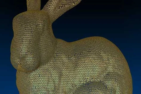
Table of content Types of Meshing Types of Meshing as per Grid Structure For those acquainted with mechanical design and reverse engineering, they can testify to the fact that the road to a new product design involves several steps. In reverse engineering, the summary of the entire process involves scanning, point cloud generation, meshing, computer-aided designing, prototyping and final production. This section covers a very crucial part of the process — Meshing or simply put, Mesh. To put a simple definition, a mesh is a network that constitutes of cells and points. Mesh generation is the practice of converting the given set of points into a consistent polygonal model that generates vertices, edges and faces that only meet at shared edges. It can have almost any shape in any size. Each cell of the mesh represents an individual solution, which when combined, results in a solution for the entire mesh. Mesh is formed of facets which are connected to each other topologically. The topology is created using following entities: These include: Types of Meshing Meshes are commonly classified into two divisions, Surface mesh and Solid mesh. Let us go through each section one by one. Surface MeshA surface mesh is a representation of each individual surface constituting a volume mesh. It consists of faces (triangles) and vertices. Depending on the pre-processing software package, feature curves may be included as well. Generally, a surface mesh should not have free edges and the edges should not be shared by two triangles. The surface should ideally contain the following qualities of triangle faces: The surface mesh generation process should be considered carefully. It has a direct influence on the quality of the resulting volume mesh and the effort it takes to get to this step. Solid Mesh Solid mesh, also known as volume mesh, is a polygonal representation of the interior volume of an object. There are three different types of meshing models that can be used to generate a volume mesh from a well prepared surface mesh. The three types of meshing models are as follows: Once the volume mesh has been built, it can be checked for errors and exported to other packages if desired. Types of Meshing as per Grid Structure A grid is a cuboid that covers entire mesh under consideration. Grid mainly helps in fast neighbor manipulation for a seed point. Meshes can be classified into two divisions from the grid perspective, namely Structured and Unstructured mesh. Let us have a look at each of these types. Structured Mesh Structured meshes are meshes which exhibits a well-known pattern in which the cells are arranged. As the cells are in a particular order, the topology of such mesh is regular. Such meshes enable easy identification of neighboring cells and points, because of their formation and structure. Structured meshes are applied over rectangular, elliptical, spherical coordinate systems, thus forming a regular grid. Structured meshes are often used in CFD. Unstructured Mesh Unstructured meshes, as the name suggests, are more general and can randomly form any geometry shape. Unlike structured meshes, the connectivity pattern is not fixed hence unstructured meshes do not follow a uniform pattern. However, unstructured meshes are more flexible. Unstructured meshes are generally used in complex mechanical engineering projects. Get access to our mesh tools library today Mesh Tools library offers a comprehensive set of operation for meshes for all your needs. Developed in C++, this library can be easily integrated in to your product. To learn more,
Read MorePoint Clouds | Point cloud formats and issues
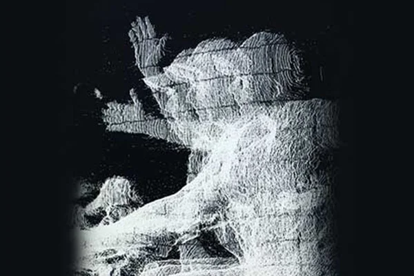
Table of content Different 3D point cloud file formats Challenges with point cloud data Whether working on a renovation project or making information data about an as-built situation, it is understandable that the amount of time and energy spent analyzing the object/project can be pretty debilitating. Technical literature over the years has come up with several methods to make a precise approach. But inarguably, the most prominent method is the application of Point Clouds. 3D scanners gather point measurements from real-world objects or photos for a point cloud that can be translated to a 3D mesh or CAD model. But what is a Point Cloud? A standard definition of point clouds would be – A point cloud collection of data points defined by a given coordinates system. In a 3D coordinates system, for example, a point cloud may determine the shape of some real or created physical system. Point clouds are used to create 3D meshes and other models used in 3D modeling for various fields, including medical imaging, architecture, 3D printing, manufacturing, 3D gaming, and various virtual reality (VR) applications. When taken together, a point is identified by three coordinates that correlate to a precise point in space relative to the end of origin. Different 3D point cloud file formats Scanning a space or an object and bringing it into designated software lets us manipulate the scans further, and stitch them together, which can be exported to be converted into a 3D model. Now there are numerous file formats for 3D modeling. Different scanners yield raw data in different formats. One needs other processing software for such files, and each & every software has its exporting capabilities. Most software systems are designed to receive a large number of file formats and have flexible export options. This section will walk you through some known and commonly used file formats. Securing the data in these common formats enables using different software for processing without approaching a third-party converter. Standard point cloud file formatsOBJ: It is a simple data format that only represents 3D geometry, color, and texture. And this format has been adopted by a wide range of 3D graphics applications. It is commonly ASCII (American Standard Code for Information Interchange). ASCII is a rooted language based on a binary that conveys information using text. Standard ASCII represents each character as a 7-bit binary number. In reverse engineering, characters are the focus of data. E57: E57 is a compact and widely used open, vendor-neutral file format for point clouds, and it can also be used to store images and data produced by laser scanners and other 3D imaging systems. Its compact, binary-based format combines the speed and accessibility of ASCII with the precision and accuracy of binary. E57 files can also represent normals, colors, and scalar field intensity. However, E57 is not universally compatible across all software platforms. PLY: The full form of PLY is the polygon file format. PLY was built to store 3D data. It uses lists of nominally flat polygons to represent objects. The aim is to store a more significant number of physical elements. It makes the file format capable of representing transparency, color, texture, coordinates, and data confidence values. It is found in ASCII and binary versions. PTS, PTX & XYZ: These three formats are familiar and compatible with most BIM software. It conveys data in lines of text. They can be easily converted and manipulated. PCG, RCS & RCP: These three formats were developed by Autodesk to meet their software suite’s demands. RCS and RCP are relatively newer. Binary point cloud file formats are better than ASCII or repurposed file types. It is because the latter is more universal and has better long-term storage capabilities. However, this type of format can be used to create a backup of the original data. If you need to convert binary point cloud files to ASCII, back up your binary files before reformatting them. This way, you can restore your data if something goes wrong. Challenges with point cloud data In reverse engineering, you may encounter several Point Cloud issues. The laser scanning procedure has catapulted product design technology to new heights. 3D data capturing system has come a long way, and we can see where it’s headed. As more and more professionals and end users are using new devices, the scanner market is rising at a quick pace. But along with a positive market change, handling and controlling the data available becomes a vital issue. These problems can result in poor quality point cloud data. Read on to learn more about five key challenges professionals working with point cloud face are: Data Quality: You must identify the quality issues in reverse engineering point cloud data. Reconstruction algorithms differ in their behavior based on the properties of point clouds. Many studies have classified the properties of point clouds by their effect on algorithms. The quality of point clouds affects the precision of the reconstructions. Point clouds produced by body scanners typically contain many duplicated and overlapping patches. These features cause a large amount of noise and redundancy in the final data. Reconstruction of free-form surfaces requires the use of clean-up meshes. This data must be transformed into a model that is consistent and accurate. Fortunately, this task is possible with the help of cloud-to-cloud alignment tools. Data Format: New devices out there in the market yield back data in a new form. Often, one needs to bring together data in different formats from different devices against a compatible software tool. It presents a not-so-easy situation. Identifying the wrong point cloud file format in reverse engineering is of great importance. Often when a company attempts to perform reverse engineering, it will be presented with a point cloud file in the wrong format. It can cause problems because the data is not in the correct format. EMPA has made it their business to work with point clouds as soon as possible. However, this doesn’t mean that you should give up
Read MoreTypes & Benefits of 3D Scanners and 3D Scanning Technologies
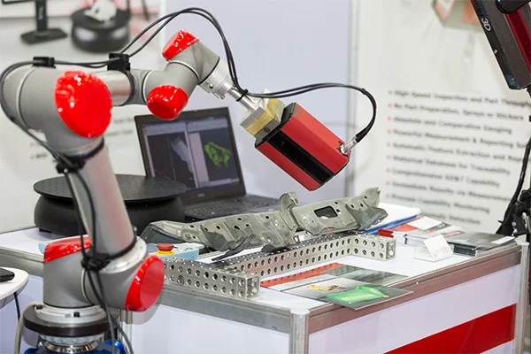
Table of content 3D Scanning Technology Types of scanners Benefits of 3D Laser Scanners As we have seen during the introduction, the first step to reverse engineering a product is through scanning with the help of 3D scanners. Early eras have seen the painstaking task of obtaining dimensions of an existing product. These methods were time-consuming and needed attention to detail from the first stage. However, with the rapid development in the scanning technology, the inception of a product has caught speed, and the chances of errors have reduced dramatically, making 3D scanning and measurement a vital part, starting from the design stage to the inspection stage. 3D laser scanning is the technology to capture a physical object’s exact size and shape using a laser beam to create a digital 3-dimensional representation of the same. 3D laser scanners produce “point clouds” of data from the surface of an object. 3D Scanning Technology 3D laser scanning efficiently takes the measurements of contoured surfaces and complex geometries, requiring vast amounts of data for accurate description. Doing this using traditional measurement methods is impractical and time-consuming. Acquiring sizes and dimensions of free-form shapes creates precise point cloud data. The basic working principle of a 3D scanner is to collect an entity’s data. It can either be:an object In reverse engineering, a laser scanner’s primary aim is to provide a lot of information about the design of an object which in the later stages gets converted to 3D CAD models, considering the compatibility of 3D scans and Computer Aided Design (CAD) software. 3D scans are even compatible with 3D printing, requiring specific computer software.3D scanning technologies vary with different physical principles and can be classified as follows:Laser triangulation 3D scanning technology: In this category, the laser scanner projects a laser beam on a surface and measures the deformation of the laser ray. Structured light 3D scanning technology: This technology involves projecting structured patterns of light on an object and acquiring a surface’s shape by measuring the light pattern’s deformation. Photogrammetric technology: It is also known as a 3D scan from photography. It reconstructs an object from 2D to 3D and has specific computational geometrical algorithms for the task. Photogrammetry is cheap, precise, and used to scan large objects such as buildings and stadiums.Photogrammetric technology Laser pulse 3D scanning technology: This unique process collects geometrical information by evaluating the time a laser beam takes to travel between its emission and reception. Computerized Tomography (CT scan): A widely used technique in the medical sector, CT scan is generally used to scan images of the human interiors. CT scans consist of scanning a part and taking a series of 2D images of various sections with X-rays. The 2D images are later superimposed on each other to imitate a 3D model. Contact-based 3D scanning technology: This process requires contact between the probe and the object, where the probe is moved firmly over the surface to acquire data. Types of scanners Apart from scanning technologies, there are various types of 3D scanners. Some are built for short- range scanning, while others are ideal for medium or long-range scanning. The building and usage of specific scanners hugely depend upon the object’s size to be scanned. The scanners for measuring small things vastly differ from those used for large-bodied objects, such as ships. Here is a summary of the types of 3D laser Scanners: Short Range 3D scanners: Short Range 3D scanners utilize either a Laser triangulation technology or Structured Light technology. Laser-based 3D scanners: These scanners employ trigonometric triangulation to capture a 3D object as millions of points. Laser scanners work by projecting a laser beam or multiple laser beams on an object and capturing its reflection with sensors located at a fixed distance from the scanners. Laser scanners come in various designs such as handheld portable units, arm-based, CMM-based, long-range, and single-point long-range trackers. Structured light 3D scanners: These are also known as white light scanners. However, most structured scanners use blue or white LED lights. The light pattern usually consists of a geometrical shape such as a bar, block, or other shape projected onto the object. The sensors consider the edge of the pattern to determine the 3D shape of the object. Blue or white light scanners are generally used to obtain outward dimensions. Medium and Long range scanners: Long-range 3D scanners are used for large objects such as buildings, ships, aircraft, and military vehicles. These scanners rotate and spin a mirror which reflects the laser outward towards the thing or areas to be 3D scanned. Arm-based scanners: Arm-based scanners are handy when measuring small minor parts, as they can be maneuvered by attaching them to the arm and is generally portable. Benefits of 3D Laser Scanners 3D scanners have contributed a lot over the years; needless to say; they come up with many benefits. Some of them are as follows:Able to scan harsh surfaces, such as shiny or dark finishes.This is strictly for handheld or other portable scanners. But given their importance, it is safe to say that the portability of scanners has played a significant role in easing up engineering.The scanning technology has enabled it to capture millions of points in less time.Scanners are less sensitive to changing light conditions and ambient light.Scanning of complex contours and geometrical figures has become more convenient with the invention of groundbreaking scanning technologies.Laser scanners have become so diverse that they are produced depending upon various projects or the objects to be scanned. The right place for your reverse engineering solutions Whether it is scanning or point cloud generation or meshing or 3D model creation, our engineers have been thoroughly trained in end-to-end reverse engineering.
Read More