Geometric Dimensioning and Tolerancing (GD&T)
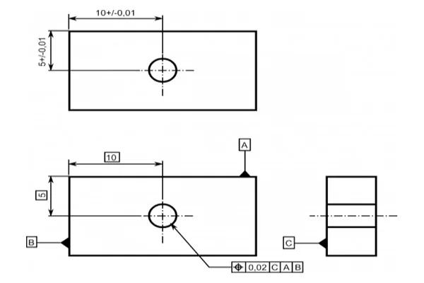
The design model is a depiction of a part design. However, the design model can never be an accurate representation of the product itself. Due to shortcomings in manufacturing and inspection processes, physical parts never match the design model exactly. An essential aspect of a design is to specify the lengths the part features may deviate from their theoretically accurate geometry. It is vital that the design intent and functionality of the part be communicated between the design engineers and the manufacturing unit. It is where the approach of GD&T comes into play. Geometric dimensioning and tolerancing or GD&T is a language of symbols and standards used on engineering drawings and models to determine the allowable deviation of feature geometry. GD&T consists of dimensions, tolerances, definitions, symbols, and rules that enable the design engineers to convey the design models appropriately. The manufacturing unit uses the language to understand the design intent. To master GD&T, one needs to understand the crucial concepts, which includes: GD&T is an efficient way to describe the dimensions and tolerances compared to traditional approximation tolerancing. The engineer might design a part with perfect geometry in CAD, but the produced part, more often than not, turns out to be not accurate. Proper use of GD&T improves quality and reduce time and cost of delivery by providing a common language for expressing design intent.
Read More