Design principles of Jigs and Fixtures
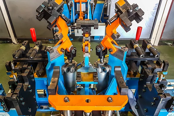
The art of metalworking has a primary concern, locating the part to be machined relative to the platform. A CNC machine starts machining at a specific point corresponding to the fixture and proceeds from there. Therefore, the preciseness with which a job is machined is dependent on the accuracy that holds in the fixture. The accurate location of every part loaded into the fixture is essential. Any deviation in part location adds to the dimensional tolerance that must be assigned to the finished pieces. Furthermore, improper supporting and securing the part in the fixture affects surface finishes by temporarily or permanently deforming it. Hence, techniques for supporting, clamping, and locating must be considered together to assure repeatability from part to part. Basic principles of Jigs and Fixtures design LOCATING POINTS: Locating the work is a prime necessity and requires suitable facilities. The correct setup ensures smooth insertion of a workpiece in the proper position and removing a workpiece from a jig without operational hassles or time consumption. The workpiece position needs to be precise with the guiding tool in the jig or setup pieces in the fixture. FOOLPROOF: A foolproof design of jigs and fixtures does not permit a tool or workpiece to be placed in any other way other than the intended one. REDUCTION OF IDLE TIME: Jigs and Fixtures must be designed in such a way that ensures smooth loading, clamping, machining, and unloading of a WEIGHT OF JIGS AND FIXTURES: A jig and fixture must be compact, easy to handle, and low cost regarding the number of materials used without giving up stiffness and rigidity. JIGS PROVIDED WITH FEET: Some jigs require feet so that they can be placed on the table firmly. MATERIALS FOR JIGS AND FIXTURES: Jigs and Fixtures are usually created with hardened materials to resist wear & tear and avoid frequent damage—for example, Mild steel, Cast iron, Die steel, High-speed steel, Caesium. CLAMPING DEVICE: A suitable clamp is rated for its strength. It should be able to hold a workpiece firmly in its position while bearing the strain of the cutting tool simultaneously, without springing. Broad rules of Jigs & Fixtures Design The 3-2-1 principle Locating a part to be machined involves mainly three steps: Supporting, Positioning, and Clamping. Two main intentions when placing a job on a jig/fixture are: An extensively used method for obtaining these objectives is the 3-2-1 principle or six degrees of freedom for part location. The 3-2-1 method is a work-holding principle where three pins are located on the 1st principle plane, i.e., either XY, YZ, ZX. And two pins are located on the 2nd plane perpendicular to the 1st plane, and at last, one pin on the plane is mutually perpendicular to the 1st and 2nd planes. The aim is to constrain the movement of the workpiece along all three axes. Design objectives of Jigs and Fixtures Before sitting down to design jigs/fixtures, the designer must consider the following points: The designer must know the basics of the process and the tools associated with it for which the jig/fixture is designed. Overall objectives to look out for a while developing such tools are: Reference: National Institute of Technology, Calicut
Read MoreWhat are Jigs and Fixtures, their Advantages, and Differences
Table of content Jigs Fixtures Differences between Jig and Fixture With the rapid advancement in manufacturing technology, consumerism has increased. Therefore, to meet the higher demands, manufacturers have developed innovative methods to produce high- quality products faster. The production process has observed the introduction of inventive manufacturing concepts such as Lean Production System, Cellular Manufacturing, Single Minute Exchange of Dies, and Tact Time Analysis. These creative approaches require a horde of efficient, cheaper tools and work-holding devices. The manufacturing company requires a simple work positioning strategy and devices for correct operations. This is to ensure: The industry has resorted to easing up the supply chain to maintain. This resulted in better and cost- effective work-holding devices that ensure better quality products, increase throughput, and reduce lead time. The requirement for the production of standard work-holding devices has paved the way for two specific terms named: Jigs and Fixtures. The jig is the device that guides the tool, while the fixture is a tool that securely and firmly holds the job in position during machining operations. Jigs In simple terms, a jig is a tool that guides the machining tool. A common type of jig is the drill jig, which guides the drill for making holes at desired locations. Using drill jigs increases the production rate drastically. These tools are usually made of metal, such as steel and aluminum, and are generally fitted with positioning devices called bushings. These tools guide the operation of machines and other equipment. Fixtures On the other hand, a fixture is a tool that firmly grips a workpiece on the machine bed accurately at the desired location. The fixture also reduces the loading, unloading, and fixing the time of the workpiece, which significantly reduces the non-productive hours. Fixtures are used for milling, turning, and grinding operations. To ensure proper alignment and hold of parts, fixtures can include a variety of locating components. Some manufacturers are even turning to 3D printing for their fixtures. Typical jigs and fixtures are made from Cast Iron or Aluminum, though steel versions are also available. These jigs and fixtures can be purchased or custom-built. They are mounted on T-Slot plates and hold a variety of work holding devices. Differences between Jig and Fixture “Jig” and “Fixture” are often referred to as synonyms, while sometimes both are used together as jigs-fixtures. Although both jig and fixture are used in the mass production process, functionally, the two are quite different tools. Let us go through the main points which differ a Jig from a fixture. Jigs Fixtures A jig controls and guides the machining tool A fixture holds and supports the component precisely for machining operations Jig ensures accuracy, repeatability, and interchangeability The fixture provides a reduction in error by holding a component firmly on a table Jigs are usually on the lighter side The fixture is bulky, rigid, and heavy Jigs can be put in place and held by hand pressure Fixtures are always placed firmly on a machine table Some of the standard jig functions are drilling, reaming, tapping, and boring Fixtures are used explicitly in milling machines, slotting machines, and shapers Jigs cost more Fixtures are not that cost-savvy compared to Jigs Jigs require intricate design operations Fixture design operations are relatively less complicated Advantages of Jigs and Fixtures Jigs and Fixtures have made manufacturing processes less time-consuming, more precise, and hassle-free from a human factor perspective. The benefits of jigs and fixtures include but are not limited to the following: Both jigs and the fixtures are used to ease machining operations and reduce the non-productive time of any mass production process. The principle of location or the 3-2-1 principle, CAD tools, and FEA tools are used to design jigs and fixtures. The following article will go through more detailed information about the 3-2-1 principle and design standards of jigs and fixtures. In the manufacturing industry, innovation is often about maximizing existing resources and building on the strengths of individual companies. Focus on jigs and fixtures helps companies increase productivity and production speed and cut overall expenses. They reduce the time required for quality control, cut down on errors, and speed up the production process. Furthermore, they are easier to use, even by semi-skilled operators. And since they are standardized, they ensure that every part produced is consistent, reducing the risk of human error.
Read MoreWhat is Mesh and what are the types of Meshing
Table of content Types of Meshing Types of Meshing as per Grid Structure For those acquainted with mechanical design and reverse engineering, they can testify to the fact that the road to a new product design involves several steps. In reverse engineering, the summary of the entire process involves scanning, point cloud generation, meshing, computer-aided designing, prototyping and final production. This section covers a very crucial part of the process — Meshing or simply put, Mesh. To put a simple definition, a mesh is a network that constitutes of cells and points. Mesh generation is the practice of converting the given set of points into a consistent polygonal model that generates vertices, edges and faces that only meet at shared edges. It can have almost any shape in any size. Each cell of the mesh represents an individual solution, which when combined, results in a solution for the entire mesh. Mesh is formed of facets which are connected to each other topologically. The topology is created using following entities: These include: Types of Meshing Meshes are commonly classified into two divisions, Surface mesh and Solid mesh. Let us go through each section one by one. Surface MeshA surface mesh is a representation of each individual surface constituting a volume mesh. It consists of faces (triangles) and vertices. Depending on the pre-processing software package, feature curves may be included as well. Generally, a surface mesh should not have free edges and the edges should not be shared by two triangles. The surface should ideally contain the following qualities of triangle faces: The surface mesh generation process should be considered carefully. It has a direct influence on the quality of the resulting volume mesh and the effort it takes to get to this step. Solid Mesh Solid mesh, also known as volume mesh, is a polygonal representation of the interior volume of an object. There are three different types of meshing models that can be used to generate a volume mesh from a well prepared surface mesh. The three types of meshing models are as follows: Once the volume mesh has been built, it can be checked for errors and exported to other packages if desired. Types of Meshing as per Grid Structure A grid is a cuboid that covers entire mesh under consideration. Grid mainly helps in fast neighbor manipulation for a seed point. Meshes can be classified into two divisions from the grid perspective, namely Structured and Unstructured mesh. Let us have a look at each of these types. Structured Mesh Structured meshes are meshes which exhibits a well-known pattern in which the cells are arranged. As the cells are in a particular order, the topology of such mesh is regular. Such meshes enable easy identification of neighboring cells and points, because of their formation and structure. Structured meshes are applied over rectangular, elliptical, spherical coordinate systems, thus forming a regular grid. Structured meshes are often used in CFD. Unstructured Mesh Unstructured meshes, as the name suggests, are more general and can randomly form any geometry shape. Unlike structured meshes, the connectivity pattern is not fixed hence unstructured meshes do not follow a uniform pattern. However, unstructured meshes are more flexible. Unstructured meshes are generally used in complex mechanical engineering projects. Get access to our mesh tools library today Mesh Tools library offers a comprehensive set of operation for meshes for all your needs. Developed in C++, this library can be easily integrated in to your product. To learn more,
Read MorePoint Cloud Operations
No output is always perfect no matter how much the technology has evolved. Even though point cloud generation has eased up manufacturing process, it comes with its own anomaly. Generally, a point cloud data is accompanied by Noises and Outliers. Noises or Noisy data means the data information is contaminated by unwanted information; such unwanted information contributes to the impurity of the data while the underlying information still dominates. A noisy point cloud data can be filtered and the noise can be absolutely discarded to produce a much refined result. If we carefully examine the image below, it illustrates a point cloud data with noises. The surface area is usually filled with extra features which can be eliminated. After carrying out Noise Reduction process, the image below illustrates the outcome, which a lot smoother data without any unwanted elements. There are many algorithms and processes for noise reduction. Outlier, on the contrary, is a type of data which is not totally meaningless, but might turn out to be of interest. Outlier is a data value that differs considerably from the main set of data. It is mostly different from the existing group. Unlike noises, outliers are not removed outright but rather, it is put under analysis sometimes. The images below clearly portray what outliers are and how the point cloud data looks like once the outliers are removed. Point Cloud Decimation We have learned how a point cloud data obtained comes with noise and outliers and the methods to reduce them to make the data more executable for meshing. Point cloud data undergoes several operations to treat the anomalies existing within. Two of the commonly used operations are Point Cloud Decimation and Point Cloud Registration. A point cloud data consists of millions of small points, sometimes even more than what is necessary. Decimation is the process of discarding points from the data to improve performance and reduce usage of disk. Decimate point cloud command reduces the size of point clouds. The following example shows how a point cloud underwent decimation to reduce the excess points. Point Cloud Registration Scanning a commodity is not a one step process. A lot of time, scanning needs to be done separately from different angles to get views. Each of the acquired data view is called a dataset. Every dataset obtained from different views needs to be aligned together into a single point cloud data model, so that subsequent processing steps can be applied. The process of aligning various 3D point cloud data views into a complete point cloud model is known as registration. The purpose is to find the relative positions and orientations of the separately acquired views, such that the intersecting regions between them overlap perfectly. Take a look at the example given below. The car door data sets have been merged to get a complete model.
Read MoreWhat is CAD | Types of CAD Models and CAD Formats
Table of content What is CAD? Types of CAD models Types of CAD formats Use of CAD What is CAD? Computer-Aided Design, aka CAD, is undoubtedly a crucial stage in product development. By definition, CAD is the acronym for Computer-Aided Design. It covers various design tools used by multiple professionals like artists, game designers, manufacturers, and design engineers. After a meshed part is aligned, it goes through surface modeling in tools such as Polyworks. It generates a non-parametric model (IGES or STEP format) or parametric modeling where a sketch of the meshed part is created instead of putting it through surfacing (.PRT format). The resultant is generally called a 3D computer-aided model or CAD model. The technology of CAD systems has tremendously helped users by performing thousands of complex geometrical calculations in the background without anyone dropping a sweat for it. CAD has its origin in early 2D drawings where one could draw objects using basic views: top, bottom, left, right, front, back, and the angled isometric view. 3D CAD programs allow users to take 2D pictures and convert them into a 3D object on the screen. In a simple definition, CAD design is converting primary design data into a more perceptible and more understandable design. Each CAD system has its algorithm for describing geometry mathematically and structurally. Types of CAD models. Everything comes with its variety, and CAD modeling is no stranger. As the technology evolved, CAD modeling came up in different styles. There are many methods of classifying them, but a broad general classification can be as follows: Two-dimensional or 2D CAD: The early version of CAD that most of us are aware of. These are 2-dimensional drawings on a flat sheet with dimensions, layouts, and other information needed to manufacture the object. The 2D CAD objects consist of lines, ovals, circles, ovals, curves, and slots. 2D CAD platforms generally come with a library of geometric images and the ability to create Bezier curves, polylines, and splines. They are also capable of generating a bill of materials (BOM). 2.5D CAD:The 2.5 D CAD are prismatic, which means they represent the depth of an object. They fall between 2D and 3D CAD, and the objects consist of geometric patterns like in 2D CAD. Three-dimensional or 3D CAD:The purpose of both 2D and 3D models is the same. But what sets 3D models apart is their ability to present more excellent details about the individual component and assembly by projecting it as a full-scale 3-dimensional object. 3D CAD offers a realistic portrayal of the CAD model. 3D models can be viewed and rotated in X, Y, or Z axes. It also shows how two objects can fit and operate, which is impossible with 2D CAD. 3D models can be further classified into three categories: 3D Wire-frame Models:These models resemble an entire object made of just wires, with the background visible through the skeletal structure. Surface Models:Surface models are the next stage of wireframe models, and they are created by joining the 3D surfaces together and look like real-life objects. Solid Models:They best represent real physical objects in a virtual environment. Unlike other models, solid models have weight, volume, and density properties. They are the most used models and serve as prototypes for engineering projects. The Boundary Representation (BREP) solid modeling links Constructive Solid Geometry (CSG) images while a hybrid systems mix CSG and BREP to attain the intended design. Types of CAD formats Different professionals use different software platforms for various reasons like cost, project requirements, features, etc. Although the software comes with its file formats, there are instances where one needs to share their project with someone else, either partners or clients, who are using different software. In such cases, it is necessary that both parties’ software understand each other’s file formats or, in other words, interoperable. As a result of this situation, it is essential to have file formats that can be accommodated in various software. CAD file formats can be broadly classified into two types: STEP: This is the most popular CAD file format of all. It is widely used and highly recommended as most software support STEP files. STEP is the acronym for Standard for the Exchange of Product Data. IGES: IGES is the acronym for Initial Graphics Exchange Specification. It is an old CAD file format that is vendor-neutral. IGES has fallen out lately since it lacks many features that newer file formats have. Parasolid: Parasolid was initially developed by Shape Data and is currently owned by Siemens PLM Software. STL: STL stands for Stereolithography which is the format for 3D information created by 3D systems. STL finds its usage mostly in 3D printers. STL describes only the outer structure or surface geometry of a physical object but doesn’t give out the color, texture, and other attributes of an object. VRML: VRML stands for Virtual Reality Modeling Language. Although it gives back more attributes than STL, a handful of software can read it. Prototyping & pilot runs (preliminary design stage) In this stage, prototypes are built and tested after several iterations, and a pilot run of the manufacturing process is conducted. This stage involves creating rapid prototypes for a concept deemed to have business relevance and value. Prototype means a ‘quick and dirty’ model rather than a refined one that will be tested and marketed later. Adjustments are carried out as required before finalizing the design. X3D: X3D is an XML-based file format for representing 3D computer graphics. COLLADA: COLLADA stands for Collaborative Design Activity and is mostly used in gaming and 3D modeling. DXF: DXF stands for Drawing Exchange Format, a pure 2D file format native to AutoCAD. Use of CAD CAD technology has placed the entire engineering process in an adrenaline mode. It is possible to mold or fold, modify, or make a new part from scratch, all with the help of CAD modeling software. The many uses of CAD are as follows:CAD generates design and layouts, details and calculations, and 3-D
Read MoreMesh – List of operations
Good cell quality of meshes translate into accurate results within optimum time after computation. But more often than not, we get a mesh output, which is far from accuracy. There are number of factors affecting a mesh, that might compromise with the final result. This chapter focuses on the various shortcomings of a mesh and their repair algorithms. Mesh Decimation/Simplification Mesh decimation/simplification is the method of reducing the number of elements used in a mesh while maintaining the overall shape, volume and boundaries preserved as much as possible. It is a type of algorithm that aims to transform a given mesh into another with fewer elements (faces, edges and vertices). The decimation process usually involves a set of user-defined quality criteria, that maintains specific properties of the original mesh as much as possible. This process reduces the complexity of a mesh. Mesh Hole-Filling To analyze a mesh model, it must be complete. Often, some mesh models carry holes in them, which must be filled. The unseen areas of the model appear as holes, which are aesthetically unsatisfying and can be a hindrance to algorithms that expect a continues mesh. The Fill Hole command fills the holes and gaps in the mesh. Note – The Fill Hole command only works on triangulated mesh and not tetrahedral mesh Mesh Refinement Certain situations arise which makes us concerned about the accuracy a model in certain areas. Such scenarios prompt us to have fine mesh in those areas to ensure accurate results. However, creating a surface mesh of the entire model with a fine mesh size may ask for unnecessary hours to analyze the fine mesh in those regions where the results are not as important to you. The answer to this issue is the usage of refinement points. A refinement point identifies a region or volume of space in which a finer mesh has to be generated. Mesh refinement can be defined by identifying an absolute size for the local mesh. Mesh refinement ends up in creating more number of elements in the specified region of the model. Mesh Smoothing Mesh smoothing is also known as mesh relaxation. Sometimes it is necessary to modify that mesh after a mesh generation. It is achieved either by changing the positions of the nodes or by removing the mesh altogether. Mesh smoothing results in the modification of mesh point positions, while the topology remains as it is.
Read More


