What are DFMA and DFMEA
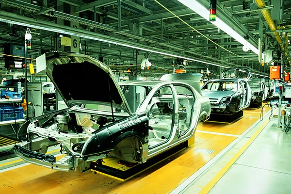
Table of content Design for Manufacturing and Assembly (DFMA) Design Failure Mode and Effect Analysis (DFMEA) During the last few decades, manufacturers have been able to source parts globally with the developments in technology. More and more manufacturers have entered the competition as it grows fierce. Companies in developing nation markets offer products at lower prices. To sustain business and achieve growth, many manufacturers are developing new products to cater to the consumers and widen it. They must be very marketable and of high quality. The Design for Manufacturing and Assembly (DFMA) method enables firms to develop quality products in lesser time and at lower production costs. Design for Manufacturing and Assembly (DFMA) Design for Manufacturing and Assembly or DFMA is a design process that targets ease of manufacturing and assembly efficiency. Simplifying the design of a product makes it possible to manufacture and assemble it in the minimum time and lower cost. DFMA approach has been used in the automotive and industrial sectors mainly. However, the process has been adopted in the construction domain as well. DFMA is a combination of two methodologies which are: DFM and DFA seek to reduce material and labor costs associated with designing and manufacturing a product. For a successful application of DFMA, the two activities should operate in unison to earn the most significant benefit. Through the DFMA approach, a company can prevent, detect, quantify, and eliminate waste and manufacturing inefficiency within a product design. Design Failure Mode and Effect Analysis (DFMEA) Design Failure Mode and Effect Analysis (DFMEA) is a systematic string of activities to identify and analyze potential systems, products, or process failures. Design Failure Mode and Effects Analysis or DFMEA focuses on finding potential design flaws and failures of components before they can significantly impact the end users of a product and the business distributing the product. The design failure mode and effect analysis – DFMEA is an ideal process for any sector where risk reduction and failure prevention are crucial, which includes: With expertise in advanced engineering, Prescient Technologies ensures maximum benefit to their client in terms of value addition, weight reduction, material selection, cost reduction, or manufacturing process selection. Visit our website for more details or send a message.
Read MoreDesigning Jigs and Fixtures
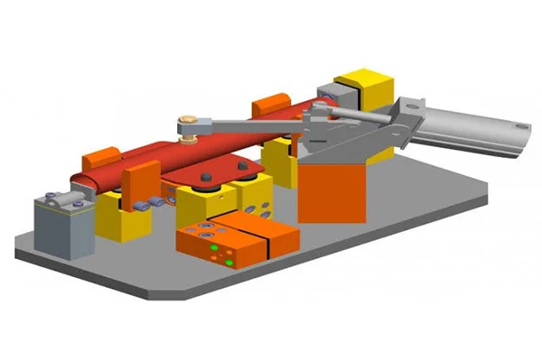
The design of jigs and fixtures is dependent on numerous factors which are analysed to achieve optimum output. Jigs should be made of rigid light materials to facilitate secure handling, as it has to be rotated severally to enable holes to be drilled from different angles. It is recommended that four feet should be provided for jigs that are not bolted on the machine tool, to enable the jig to wobble if not well positioned on the table and thereby alert the operator. Drill jigs provide procedures for proper location of the work-piece concerning the cutting tool, tightly clamp and rigidly support the work-piece during machining, and also guide the tool position and fasten the jig on the machine tool. To achieve their expected objectives, jigs and fixtures consist of many elements: The factors below are to be reflected upon during design, production, and assembly of jigs and fixtures due to the targeted increase in throughput, quality of products, interchangeability, and more accuracy. Elements of Jigs and Fixtures The significant features of Jigs and Fixtures are: The body: The body is the most outstanding element of jigs and fixtures. It is constructed by welding of different slabs and metals. After the fabrication, it is often heat-treated for stress reduction as its main objective is to accommodate and support the job. Clamping devices: The clamping devices must be straightforward and easy to operate, without sacrificing efficiency and effectiveness. Apart from holding the work-piece firmly in place, the clamping devices are capable of withholding the strain of the cutting tool during operations. The need for clamping the work-piece on the jig or fixture is to apply pressure and press it against the locating components, thereby fastening it in the right position for the cutting tools. Locating devices: Thepin is the most popular device applied for the location of work-piece in jigs and fixtures.The pin’s shank is press-fitted or driven into a jig or fixture. The locating width of the pin is made bigger than the shank to stop it from being pressed into the jig or fixture body because of the weight of the cutting tools or work-piece. It is made with hardened steel. Jig bushing or tool guide:Guiding parts like jig bushings and templates are used to locate the cutting tool relative to the component being machined. Jig bushes are applied in drilling and boring, which must be wear resistant, interchangeable, and precise. Bushes are mainly made of a reliable grade of tool steel to ensure hardening at a low temperature and also reduce the risk of fire crackling. Selection of Materials There is a wide range of materials from where jigs and fixtures could be made, to resist tear and wear, the materials are often tempered and hardened. Also, phosphor bronze and other non-ferrous metals, as well as composites, and nylons for wear reduction of the mating parts, and damage prevention to the manufacturing part is used. Some of the materials are discussed below: Other materials for the making of jigs and fixtures include Nylon and Fibre, steel castings, stainless steel, cast iron, high tensile steels, case hardening steels, and spring steels. Reference Charles ChikwenduOkpala, EzeanyimOkechukwu C “The Design and Need for Jigs and Fixtures in Manufacturing” Science Research.Vol. 3, No. 4, 2015, pp. 213-219. DOI: 10.11648/j.sr.20150304.19
Read More
