Faceted Modeling and NURBS
- Home
- Blog Details

- September 4 2019
- admin
Modern CAD systems and CAD packages enable designers to model objects and retrieve them in their formats. Some formats are interchangeable while some enforce restrictions, upon which, it becomes difficult to transfer an object model from one form to another.
This article describes some of the most used CAD formats in the industry. But before we look into various CAD formats, it is essential to understand the concept of Faceted geometry and Analytic geometry (NURBS).
FACETED GEOMETRY
Faceted geometry, also known as discrete geometry, are models which consist of groups of polygons which is often triangles.
Most Computer-Aided Design (CAD) systems typically use continuous surface and edge definitions based on NURBS. CAE simulations break down this NURBS representation into facets by a process known as meshing. The faceted models are quite appealing to engineering marketing, as such simulations are less bothered with exact physical reality and tend to emphasize on creating eye-catching visuals, such as airflow over a car, which can be incorporated into a marketing brochure. File formats typically used for faceted models are: .3ds, .dxf, .obj, .stl (Stereolithography).
Almost all the faceted formats, except for STL, reflect material properties such as glass and metal by providing groupings of facets. However, such groupings are inadequate for a CAE simulation.
ANALYTIC GEOMETRY (NURBS)
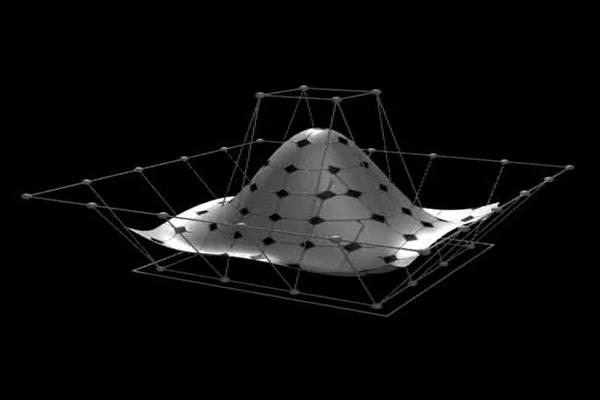
NURBS or Non-uniform rational basis spline describes curves and surfaces with mathematical functions, and form the most common analytic geometry representations. The NURBS geometry has unlimited resolution. The NURBS definition defines the location of the boundary points and uses control points with slope definition to determine the internal shape of curves and surfaces, thereby enabling a great deal of flexibility. NURBS geometry is typically produced in CAD systems such as CATIA, Pro/Engineer, Solidworks, NX, etc. A significant drawback of NURBS geometry is that they are generally specific to the CAD packages that created them, and interchanging formats can be error-prone and inaccurate.
DIFFERENCE BETWEEN FACETED GEOMETRY AND ANALYTIC GEOMETRY (NURBS)
| Faceted geometry | NURBS geometry |
| Facets are always guaranteed to comply with the original definition | In NURBS geometry, different levels of model detail are created without losing fidelity |
| Faceted geometry describes a shape as a mesh, points usually connected by triangles | Analytic geometry defines curves and surfaces with mathematical functions |
| Faceted geometry has limited resolution | NURBS geometry has unlimited resolution |
| Evaluating a faceted surface, one can get a shape defined by linear interpolation between known discrete points | One can assess a NURBS surface anywhere and get coordinates lying on the surface |
| Simple definition | Includes topology |
| Cons of Faceted geometry | Cons of NURBS geometry |
| Fixed resolution | More computing intense |
| No topology | High data exchange |
Although faceted geometry has its use, NURBS geometry is superior for design and manufacturing processes. Due to the high demands on geometric precision, NURBS geometry finds its place in CAE applications. But if the modeling requirements ask for stunning visuals, faceted models are worth giving a try.

