Product Tear Down Analysis
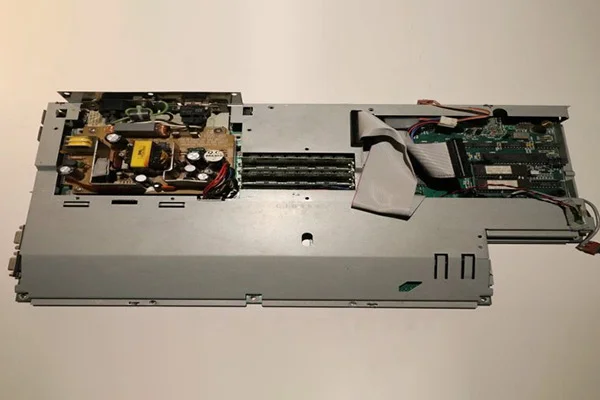
Table of content What is a product teardown? Material Selection Responsibilities of a product teardown team Pre-requisites for a product teardown workshop Length of a product teardown workshop Knowledge and product improvement How do you determine procurement costs for product design, materials, and specifications? A superb way to get valuable insights and pinpoint design improvement and cost reduction opportunities is through a product teardown analysis. What is a product teardown? In simple words, the process of disassembling a part to understand how its construction and its functionalities are known as product teardown. This technique helps companies understand their products’ components, manufacturing processes, and cost structures. These data can then be used to develop new concepts. A product teardown process is an orderly way to know about a particular product and identify its parts and system functionality to recognize modeling improvement and cost reduction opportunities. Unlike the traditional costing method, teardown analysis collects information to determine product quality and price desired by the consumers. Companies can understand their competitor’s product, on what ground it differs from their own, and the manufacturing cost associated. The three primary reasons for a product teardown analysis are: Breakdown and Analysis It involves understanding the current technology, functionalities, and components of a product, identifying its strengths and weaknesses, and establishing areas for improvement. Benchmarking Benchmarking establishes a baseline in terms of understanding and representation of the product. It provides a comparison of new conceptual designs. Knowledge and product improvement It involves gaining engineering knowledge to enact new room for concept development. The entire product teardown process can be summed up in five steps: The product teardown study technique has proven to be suitable for obtaining crucial data about the manufacturing method, components, build-up model, functionality, and competitors’ strategies to improve and come up with a more refined version of a product. Material Selection Material selection stands out to be one of the most crucial aspects of engineering design as it determines the design’s reliability in terms of industrial and economic viewpoints. A great design needs appropriate material combinations, or it will fail to be a profitable product. Engineers need to choose the best materials for the same, and there are several criteria they rely upon, such as property and its reaction to given conditions. Some important points to be included are: Mechanical properties: A design needs to go through various manufacturing practices depending on the material. The primary goal is to prevent the failure of the product from a material viewpoint and ensure service fit. The materials are subject to stress, load, strength, and temperature variations. Wear of materials: Most of the time, chances are that materials are contacting each other in a product. It can be seen in the case of gears. The selected materials should be able to withstand wear and tear. Corrosion: This is a condition where the importance of material selection can be witnessed the most. It is evident in products open to the environment for an extended period. Materials like iron are highly prone to corrosion. So it is essential to make that the material is corrosion-resistant and capable of being used for the product. Manufacturing: Although the material is fit to be used for a product, it has to be appropriate for the manufacturing process. Improper machining can lead to a faulty product, and incorrect machining stems from an inability to put manufacturing functions of materials. Cost: Cost is a crucial fact to consider while selecting materials. Certain metals are rare to obtain, considering their availability and lengthy refining process. Although the cost factor can be neglected when performance is given priority, overall associated costs should be considered. There is a reason why plastics have massively replaced metals in the manufacturing process. Responsibilities of a product teardown team The responsibilities of a product teardown team can vary widely depending on the company and the type of product. Some of the most important goals of a product teardown team include: assessing the total cost of manufacturing the product and determining general overhead costs. Other team members’ duties may involve reducing labor and material costs and identifying areas for improvement. Often, a product teardown team will also be responsible for establishing benchmarks and determining where improvements can be made. The product teardown team also consists of people with extensive experience in the industry. This team will help startups evaluate their products and identify critical areas for improvement. By taking apart products, they’ll learn the process that goes into the design of each product and provide evidence-based recommendations to improve its structure. Pre-requisites for a product teardown workshop There are several different product teardown workshops, including the Japanese style, which has been used successfully in Japan since the 1970s. Every major Japanese corporation has adopted this style of workshop. Most western teardown methods focus on visual displays and lack a detailed analysis of products. In contrast, the Japanese process forces participants to examine the product in detail and compare it to its competitors. Marketers and design executives can use the results of this workshop to improve their products. Before you conduct a product teardown workshop, you must be sure to secure your products. If the products are your competitors, you will need to carry out rigorous non-destructive performance testing. Your workshop should also include data recording. Depending on the nature of the workshop, the requirements may vary from one client to the next. Length of a product teardown workshop The duration of a product teardown workshop will depend on the nature of the item being analyzed. Some workshops are as long as four days, while others are shorter, depending on the client’s needs. Participants will learn about all teardown methods and how to implement them in a team workshop setting. Often, these workshops include hands-on, creative teardown of products. But the exact length of a product teardown workshop depends on the number of participants and the types of products they are analyzing. To maximize the workshop’s effectiveness, make sure participants are aware
Read MoreTypes of Jigs and Fixtures
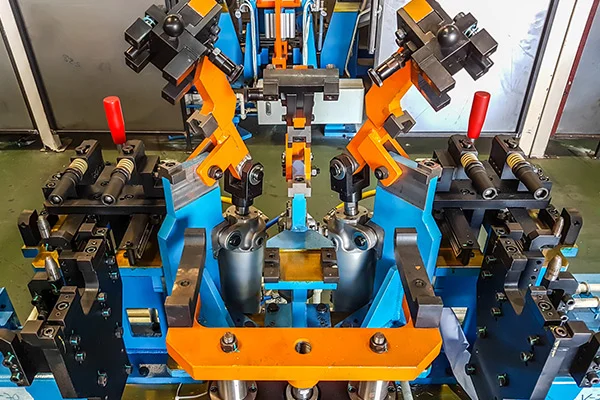
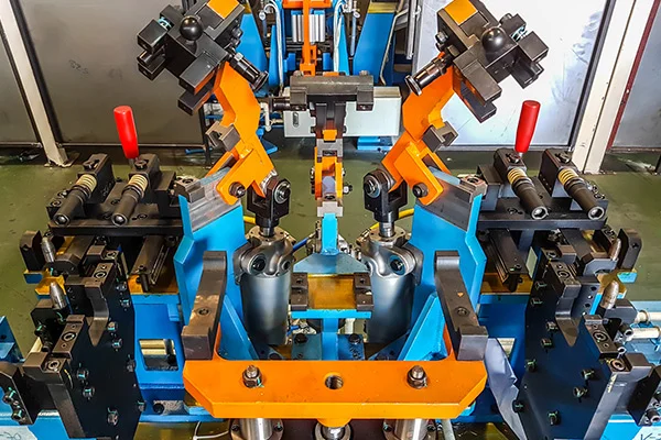
Table of content Types of Jigs Types of Fixtures We know that jigs and fixtures are the devices that help in the machining of jobs and reduce the human efforts required for producing these parts. It has been explained why a center lathe is an ideal machine tool for creating individual pieces of different shapes and sizes. Still, for manufacturing similar objects in high numbers, its use is not economical. Different objects may require drilling, milling, planing, grinding machines, etc. Specific tools are necessary for producing these objects in identical shapes and sizes on a mass scale by holding and locating tasks to minimize the repetition work. That is when various types of jigs and fixtures come into play. Considering the variety in the nature of jobs to be machined, the quality, and the associated functions, the type of jig and fixture varies. Following are the various kinds of jigs and fixtures. Types of Jigs Template Jig: The template jig is the simplest of all the models. The plate, having two holes, acts as a template fixed on the component to be machined. The drill is guided through these template holes, and the required holes are drilled on the workpiece at the same relative positions as on the template. Plate Jig: A plate jig improves the template jig by incorporating drill bushes on the template. The plate jig is employed to drill holes on large parts, maintaining accurate spacing with each other. Channel Jig: Channel jig is a simple type of jig having a channel-like cross-section. The component is fitted within the channel and is located and clamped by rotating the knurled knob. The tool is guided through the drill bush. Diameter Jig: A diameter jig is used to drill radial holes on a cylindrical or spherical workpiece. Leaf Jig: The leaf jig has a leaf that may be swung open or closed on the work for loading or loading purposes. Ring Jig: Ring jig is employed to drill holes on circular flanged parts. The work is securely clamped on the drill body, and the holes are drilled by guiding the tool through drill bushes. Box Jig: Box jig is of box-like construction within which the work is rigidly held so that it can be drilled or machined from different angles at a single setting depending on which face of the jig is turned toward the tool. Ensure top notch tool & fixture design Our team of experts having knowledge of various manufacturing processes enables them to design & develop high precision tools without any impact on required shape/profile. Visit our website for more details. Types of Fixtures Turning Fixtures: These fixtures are generally mounted on the nose of the machine spindle or a faceplate, and the workpieces hold them. The fixture may have to be provided with a counterweight or balance the unbalance fixture whenever necessary. Milling Fixtures: Milling fixtures are typically mounted on the nose of the machine spindle or a faceplate, and the workpieces hold them. The table is shifted and set in the proper position about the cutter. The workpieces are located in the base of the fixture and clamped before starting the operation. Broaching Fixtures: Broaching fixtures are used on different broaching machines to locate, hold and support the workpieces during the operations, such as keyway broaching operations, such as keyway broaching, hole broaching, etc. Indexing Fixtures: Several components need machining on different surfaces such that their machined surface surfaces or forms are evenly spaced. Such elements must be indexed equally as many as the number of surfaces to be machined. The holding devices (jigs or fixtures) used are made to carry a suitable indexing mechanism. A fixture having such a device is known as an indexing fixture. Grinding Fixtures: These fixtures may be the standard work-holding devices, such as chucks, mandrels, chuck with shaped jaws, magnetic chucks, etc. For external surface grinding, cylindrical grinding utilizes plain or tapered mandrels. The workpiece is located and held on the mandrel with the help of the bore so that the external surface may be machined truly concentric to the bore. For internal grinding, the chuck is the most standard fixture. For holding irregularly shaped components, the fixture is designed the same as turning or boring fixtures. Boring Fixtures: This fixture incorporates almost all the prevailing principles of jig and fixture design; their construction need not be as sturdy as that of the milling fixtures because they never have to bear as heavy cutting loads as involved in milling fixtures because they never have to endure as heavy cutting loads as involved in milling operations. Tapping Fixtures: Tapping fixtures are specially designed to position and firmly secure identical workpieces to cut internal threads in drilled holes. Odd-shaped and unbalanced components will always need such fixtures, especially when the tapping operation is to be carried out repeatedly on a mass scale on such parts. Duplex Fixtures: It is the name given to the fixture which holds two similar components simultaneously and facilitates simultaneously machining of these components at two separate stations. Welding Fixtures: Welding fixtures are carefully designed to hold and support the various components welded in proper locations and prevent distortions in welded structures. For this, the locating element needs to be careful; clamping has to be light but firm, and the placement of clamping elements has to be clear of the welding area. The fixture must be pretty stable and rigid to withstand the welding stresses. Assembly Fixtures: The function of these fixtures is to hold different components together in their proper relative position when assembling them. Source:The Engineers post, https://www.theengineerspost.com/jigs-and-fixturesJigs & Fixtures with differences, Types of Jigs & Fixtures and Constructional details of Jigs & Fixtures, Mechtalk
Read MoreDesigning Jigs and Fixtures
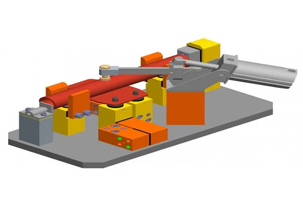
The design of jigs and fixtures is dependent on numerous factors which are analysed to achieve optimum output. Jigs should be made of rigid light materials to facilitate secure handling, as it has to be rotated severally to enable holes to be drilled from different angles. It is recommended that four feet should be provided for jigs that are not bolted on the machine tool, to enable the jig to wobble if not well positioned on the table and thereby alert the operator. Drill jigs provide procedures for proper location of the work-piece concerning the cutting tool, tightly clamp and rigidly support the work-piece during machining, and also guide the tool position and fasten the jig on the machine tool. To achieve their expected objectives, jigs and fixtures consist of many elements: The factors below are to be reflected upon during design, production, and assembly of jigs and fixtures due to the targeted increase in throughput, quality of products, interchangeability, and more accuracy. Elements of Jigs and Fixtures The significant features of Jigs and Fixtures are: The body: The body is the most outstanding element of jigs and fixtures. It is constructed by welding of different slabs and metals. After the fabrication, it is often heat-treated for stress reduction as its main objective is to accommodate and support the job. Clamping devices: The clamping devices must be straightforward and easy to operate, without sacrificing efficiency and effectiveness. Apart from holding the work-piece firmly in place, the clamping devices are capable of withholding the strain of the cutting tool during operations. The need for clamping the work-piece on the jig or fixture is to apply pressure and press it against the locating components, thereby fastening it in the right position for the cutting tools. Locating devices: Thepin is the most popular device applied for the location of work-piece in jigs and fixtures.The pin’s shank is press-fitted or driven into a jig or fixture. The locating width of the pin is made bigger than the shank to stop it from being pressed into the jig or fixture body because of the weight of the cutting tools or work-piece. It is made with hardened steel. Jig bushing or tool guide:Guiding parts like jig bushings and templates are used to locate the cutting tool relative to the component being machined. Jig bushes are applied in drilling and boring, which must be wear resistant, interchangeable, and precise. Bushes are mainly made of a reliable grade of tool steel to ensure hardening at a low temperature and also reduce the risk of fire crackling. Selection of Materials There is a wide range of materials from where jigs and fixtures could be made, to resist tear and wear, the materials are often tempered and hardened. Also, phosphor bronze and other non-ferrous metals, as well as composites, and nylons for wear reduction of the mating parts, and damage prevention to the manufacturing part is used. Some of the materials are discussed below: Other materials for the making of jigs and fixtures include Nylon and Fibre, steel castings, stainless steel, cast iron, high tensile steels, case hardening steels, and spring steels. Reference Charles ChikwenduOkpala, EzeanyimOkechukwu C “The Design and Need for Jigs and Fixtures in Manufacturing” Science Research.Vol. 3, No. 4, 2015, pp. 213-219. DOI: 10.11648/j.sr.20150304.19
Read MoreDesign principles of Jigs and Fixtures
The art of metalworking has a primary concern, locating the part to be machined relative to the platform. A CNC machine starts machining at a specific point corresponding to the fixture and proceeds from there. Therefore, the preciseness with which a job is machined is dependent on the accuracy that holds in the fixture. The accurate location of every part loaded into the fixture is essential. Any deviation in part location adds to the dimensional tolerance that must be assigned to the finished pieces. Furthermore, improper supporting and securing the part in the fixture affects surface finishes by temporarily or permanently deforming it. Hence, techniques for supporting, clamping, and locating must be considered together to assure repeatability from part to part. Basic principles of Jigs and Fixtures design LOCATING POINTS: Locating the work is a prime necessity and requires suitable facilities. The correct setup ensures smooth insertion of a workpiece in the proper position and removing a workpiece from a jig without operational hassles or time consumption. The workpiece position needs to be precise with the guiding tool in the jig or setup pieces in the fixture. FOOLPROOF: A foolproof design of jigs and fixtures does not permit a tool or workpiece to be placed in any other way other than the intended one. REDUCTION OF IDLE TIME: Jigs and Fixtures must be designed in such a way that ensures smooth loading, clamping, machining, and unloading of a WEIGHT OF JIGS AND FIXTURES: A jig and fixture must be compact, easy to handle, and low cost regarding the number of materials used without giving up stiffness and rigidity. JIGS PROVIDED WITH FEET: Some jigs require feet so that they can be placed on the table firmly. MATERIALS FOR JIGS AND FIXTURES: Jigs and Fixtures are usually created with hardened materials to resist wear & tear and avoid frequent damage—for example, Mild steel, Cast iron, Die steel, High-speed steel, Caesium. CLAMPING DEVICE: A suitable clamp is rated for its strength. It should be able to hold a workpiece firmly in its position while bearing the strain of the cutting tool simultaneously, without springing. Broad rules of Jigs & Fixtures Design The 3-2-1 principle Locating a part to be machined involves mainly three steps: Supporting, Positioning, and Clamping. Two main intentions when placing a job on a jig/fixture are: An extensively used method for obtaining these objectives is the 3-2-1 principle or six degrees of freedom for part location. The 3-2-1 method is a work-holding principle where three pins are located on the 1st principle plane, i.e., either XY, YZ, ZX. And two pins are located on the 2nd plane perpendicular to the 1st plane, and at last, one pin on the plane is mutually perpendicular to the 1st and 2nd planes. The aim is to constrain the movement of the workpiece along all three axes. Design objectives of Jigs and Fixtures Before sitting down to design jigs/fixtures, the designer must consider the following points: The designer must know the basics of the process and the tools associated with it for which the jig/fixture is designed. Overall objectives to look out for a while developing such tools are: Reference: National Institute of Technology, Calicut
Read MoreWhat are Jigs and Fixtures, their Advantages, and Differences
Table of content Jigs Fixtures Differences between Jig and Fixture With the rapid advancement in manufacturing technology, consumerism has increased. Therefore, to meet the higher demands, manufacturers have developed innovative methods to produce high- quality products faster. The production process has observed the introduction of inventive manufacturing concepts such as Lean Production System, Cellular Manufacturing, Single Minute Exchange of Dies, and Tact Time Analysis. These creative approaches require a horde of efficient, cheaper tools and work-holding devices. The manufacturing company requires a simple work positioning strategy and devices for correct operations. This is to ensure: The industry has resorted to easing up the supply chain to maintain. This resulted in better and cost- effective work-holding devices that ensure better quality products, increase throughput, and reduce lead time. The requirement for the production of standard work-holding devices has paved the way for two specific terms named: Jigs and Fixtures. The jig is the device that guides the tool, while the fixture is a tool that securely and firmly holds the job in position during machining operations. Jigs In simple terms, a jig is a tool that guides the machining tool. A common type of jig is the drill jig, which guides the drill for making holes at desired locations. Using drill jigs increases the production rate drastically. These tools are usually made of metal, such as steel and aluminum, and are generally fitted with positioning devices called bushings. These tools guide the operation of machines and other equipment. Fixtures On the other hand, a fixture is a tool that firmly grips a workpiece on the machine bed accurately at the desired location. The fixture also reduces the loading, unloading, and fixing the time of the workpiece, which significantly reduces the non-productive hours. Fixtures are used for milling, turning, and grinding operations. To ensure proper alignment and hold of parts, fixtures can include a variety of locating components. Some manufacturers are even turning to 3D printing for their fixtures. Typical jigs and fixtures are made from Cast Iron or Aluminum, though steel versions are also available. These jigs and fixtures can be purchased or custom-built. They are mounted on T-Slot plates and hold a variety of work holding devices. Differences between Jig and Fixture “Jig” and “Fixture” are often referred to as synonyms, while sometimes both are used together as jigs-fixtures. Although both jig and fixture are used in the mass production process, functionally, the two are quite different tools. Let us go through the main points which differ a Jig from a fixture. Jigs Fixtures A jig controls and guides the machining tool A fixture holds and supports the component precisely for machining operations Jig ensures accuracy, repeatability, and interchangeability The fixture provides a reduction in error by holding a component firmly on a table Jigs are usually on the lighter side The fixture is bulky, rigid, and heavy Jigs can be put in place and held by hand pressure Fixtures are always placed firmly on a machine table Some of the standard jig functions are drilling, reaming, tapping, and boring Fixtures are used explicitly in milling machines, slotting machines, and shapers Jigs cost more Fixtures are not that cost-savvy compared to Jigs Jigs require intricate design operations Fixture design operations are relatively less complicated Advantages of Jigs and Fixtures Jigs and Fixtures have made manufacturing processes less time-consuming, more precise, and hassle-free from a human factor perspective. The benefits of jigs and fixtures include but are not limited to the following: Both jigs and the fixtures are used to ease machining operations and reduce the non-productive time of any mass production process. The principle of location or the 3-2-1 principle, CAD tools, and FEA tools are used to design jigs and fixtures. The following article will go through more detailed information about the 3-2-1 principle and design standards of jigs and fixtures. In the manufacturing industry, innovation is often about maximizing existing resources and building on the strengths of individual companies. Focus on jigs and fixtures helps companies increase productivity and production speed and cut overall expenses. They reduce the time required for quality control, cut down on errors, and speed up the production process. Furthermore, they are easier to use, even by semi-skilled operators. And since they are standardized, they ensure that every part produced is consistent, reducing the risk of human error.
Read MoreWhat is CAD Customization & Automation?
Table of content Steps for Creating a CAD Customization How CAD Customization is done Benefits of CAD Customization CAD Customization and Automation Perks of Automation with CAD Customization There is no doubt that computer-aided design or CAD software has changed the game of manufacturing altogether. The advent of CAD customization has provided immense value to design and production. But what is CAD customization? The manufacturing industry has been using CAD software for some time now. These are when engineering departments, R&D centers & Design departments use Computer-Aided Design (CAD) to ease the product development process, thereby reducing the entire cycle time. CAD software makes our working fast, efficient & accurate. While CAD software offers available tools, it is hard to fathom what each user may find helpful to accomplish particular tasks. Such limitations have pushed the minds of CAD system developers to come up with the capability of customizing their software to cater to their needs. With CAD customization, it is possible to modify or create new tools better suited to our needs. One of the significant improvements we can get with customization is to replace a series of commands with a single tool that accomplishes the task. CAD customization is creating specific enhancements or tools to support CAD software. As the name suggests, CAD customization means customizing or configuring OOTB (out of the box) CAD software to suit the specific needs of a particular organization. CAD customization predominantly involves developing supporting tools for CAD software. It is mainly customized which suits a client’s particular requirements. CAD software built en-masse might not satisfy the needs of every condition, as many organizations have their specific criteria. That is when customizing CAD software comes into play. Customizing existing CAD software is perhaps the fastest and most economical way of getting the work done. Steps for Creating a CAD Customization Before developing customized CAD software, make some preparations as follows: How CAD Customization is done Most CAD systems provide the following two mechanisms: Record-Edit-Play of a macro or VB code VBA stands for Visual Basic Applications, an event-driven programming language by Microsoft. It also allows integration with other applications that use VBA. The implementation of VBA in CAD customization is easy to learn and use. Developers can create application prototypes and receive feedback on designs quickly. VBA provides a highly efficient way for manipulating CAD objects and exchanging data with other applications. Develop an Add-On using Open APIs or toolkits Another method for customizing CAD software is developing add-ons using open-source API and toolkits. One can build API implementations by using a developer toolkit. Nowadays, many API’s come as open-source, which makes the whole operation a lot smoother. APIs can be fabricated as per the requirements and applied as an added feature. One crucial factor is that the API must be compatible with the CAD software. Benefits of CAD Customization Customization of CAD software has indeed introduced us to many benefits, which are as follows: CAD Customization and Automation Design Automation is a knowledge-based process where various engineering concepts are applied in real-time product development. Overlapping CAD customization with automation brings lots of advantages to the table. Since designs are customized per requirements, the outcome is quite precise and enables quick modifications. A good practice is integrating CAD customization with design, process, and systems automation when customizing CAD software. Perks of Automation with CAD Customization: Do you want to have your own customized CAD software? Prescient Technologies has a long list of clients who benefitted a lot from a customized CAD software specifically created for their needs. If you wish to look into our portfolio..
Read MoreWhy CAD Customization is needed
As previously stated; one might encounter complex design situations in engineering scenarios. Earlier, designs were drawn on sheets with pen and necessary scaling instruments and manufactured manually using old school techniques. But now, with the advent of CAD customization, the entire work-process has become easier and smoother than ever. When CAD customization is integrated in CAD software application, a number of advantages occur. With CAD customization, the production of a drawing and design of a mechanical component can be generated with great accuracy. This facilitates the engineers to have tools to make quick modifications to any issues found in the design. The design can be customized according to the needs outlined before or after the CAD design is generated. Need for CAD Customization Implementing a functionality that does not exist in the OOTB package: The activity of CAD customization is carried out when a particular organization needs tailor made CAD software to address their need. It might be a separate functionality that a specific task needs or it might be about a format. Challenges with CAD customization Like every other entity out there, CAD customization comes with its own drawback. One big challenge with CAD customization is keeping it in sync with the latest technology in the market. Also, every CAD software is gets its new releases so it becomes quite hectic to keep a check and customizing accordingly. We have learned before how add-ons/plug-ins has been introduced to add new features to CAD software. Such add-ons are also prone to updates which need to be worked upon to make it compatible with customized software. Modern technology, however, is working its way towards making the process of updating and customizing a more lenient process.
Read MoreOutsourcing Product Development
Outsourcing development activities has become an essential component of any successful business strategy these days. As the global competitive market is gradually changing, product based companies are going against established norms following the trend of outsourcing activities. This article discusses about the logic behind outsourcing product development, elaborates on its benefits and discusses the other aspects to be considered when outsourcing product development. What is Outsourced Product Development? The outsourcing of specific activities or all activities related to the development and maintenance of a product is known as Outsourced Product Development. Outsourcing enables product companies to get access into an untapped product-building expertise and global talent pools available with service providers. This helps in exchange of technology and varied work-process. Why Outsource Product Development? Every decision making panel of an organization stumbles upon a vital question—whether to develop a product in-house or outsource the same to a third-party expertise. The product development market is becoming more competitive and mature. As the competition intensifies, product companies are under immense pressure to periodically release new versions in the market. Being an intensive activity, product development requires a lot of attention. The top management can’t afford to put all the emphasis on one activity, while overlooking the other phases of product development. It will end up affecting the profitability of the company. When to outsource product development? A typical product lifecycle involves the following activities: product development, product reengineering and migration, product maintenance, product implementation, and product testing. A product based company can choose to outsource one or more of these activities or it can outsource the entire string related to a particular product to a service providing firm. The question, however remains as to when outsource an activity. There are several factors to be taken into account before outsourcing product development. It varies with company to company. Sometimes it is even seasonal and based on current marketing trends. Some factor can be summarized like this: Benefits of outsourcing product development OPD has many benefits. A product owner need not worry about the outcome or excess expenditure if the activity is in right hands. Correct and well planned outsourcing saves a product company time, expenditure on systems and manpower, legal hassles. The best part is exchange of domain knowledge between the product company and the OPD, something that ensures better output in the future.
Read MoreWhat is Mesh and what are the types of Meshing
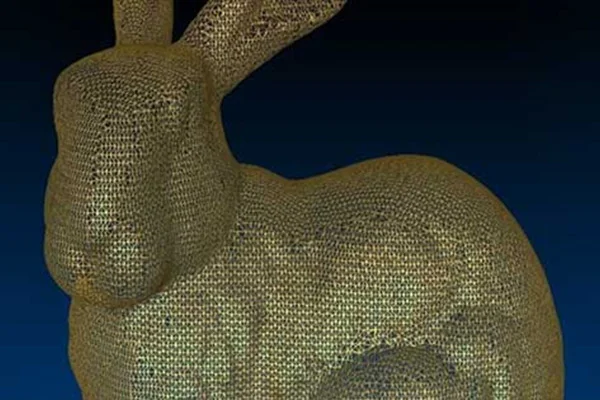
Table of content Types of Meshing Types of Meshing as per Grid Structure For those acquainted with mechanical design and reverse engineering, they can testify to the fact that the road to a new product design involves several steps. In reverse engineering, the summary of the entire process involves scanning, point cloud generation, meshing, computer-aided designing, prototyping and final production. This section covers a very crucial part of the process — Meshing or simply put, Mesh. To put a simple definition, a mesh is a network that constitutes of cells and points. Mesh generation is the practice of converting the given set of points into a consistent polygonal model that generates vertices, edges and faces that only meet at shared edges. It can have almost any shape in any size. Each cell of the mesh represents an individual solution, which when combined, results in a solution for the entire mesh. Mesh is formed of facets which are connected to each other topologically. The topology is created using following entities: These include: Types of Meshing Meshes are commonly classified into two divisions, Surface mesh and Solid mesh. Let us go through each section one by one. Surface MeshA surface mesh is a representation of each individual surface constituting a volume mesh. It consists of faces (triangles) and vertices. Depending on the pre-processing software package, feature curves may be included as well. Generally, a surface mesh should not have free edges and the edges should not be shared by two triangles. The surface should ideally contain the following qualities of triangle faces: The surface mesh generation process should be considered carefully. It has a direct influence on the quality of the resulting volume mesh and the effort it takes to get to this step. Solid Mesh Solid mesh, also known as volume mesh, is a polygonal representation of the interior volume of an object. There are three different types of meshing models that can be used to generate a volume mesh from a well prepared surface mesh. The three types of meshing models are as follows: Once the volume mesh has been built, it can be checked for errors and exported to other packages if desired. Types of Meshing as per Grid Structure A grid is a cuboid that covers entire mesh under consideration. Grid mainly helps in fast neighbor manipulation for a seed point. Meshes can be classified into two divisions from the grid perspective, namely Structured and Unstructured mesh. Let us have a look at each of these types. Structured Mesh Structured meshes are meshes which exhibits a well-known pattern in which the cells are arranged. As the cells are in a particular order, the topology of such mesh is regular. Such meshes enable easy identification of neighboring cells and points, because of their formation and structure. Structured meshes are applied over rectangular, elliptical, spherical coordinate systems, thus forming a regular grid. Structured meshes are often used in CFD. Unstructured Mesh Unstructured meshes, as the name suggests, are more general and can randomly form any geometry shape. Unlike structured meshes, the connectivity pattern is not fixed hence unstructured meshes do not follow a uniform pattern. However, unstructured meshes are more flexible. Unstructured meshes are generally used in complex mechanical engineering projects. Get access to our mesh tools library today Mesh Tools library offers a comprehensive set of operation for meshes for all your needs. Developed in C++, this library can be easily integrated in to your product. To learn more,
Read MorePoint Cloud Operations
No output is always perfect no matter how much the technology has evolved. Even though point cloud generation has eased up manufacturing process, it comes with its own anomaly. Generally, a point cloud data is accompanied by Noises and Outliers. Noises or Noisy data means the data information is contaminated by unwanted information; such unwanted information contributes to the impurity of the data while the underlying information still dominates. A noisy point cloud data can be filtered and the noise can be absolutely discarded to produce a much refined result. If we carefully examine the image below, it illustrates a point cloud data with noises. The surface area is usually filled with extra features which can be eliminated. After carrying out Noise Reduction process, the image below illustrates the outcome, which a lot smoother data without any unwanted elements. There are many algorithms and processes for noise reduction. Outlier, on the contrary, is a type of data which is not totally meaningless, but might turn out to be of interest. Outlier is a data value that differs considerably from the main set of data. It is mostly different from the existing group. Unlike noises, outliers are not removed outright but rather, it is put under analysis sometimes. The images below clearly portray what outliers are and how the point cloud data looks like once the outliers are removed. Point Cloud Decimation We have learned how a point cloud data obtained comes with noise and outliers and the methods to reduce them to make the data more executable for meshing. Point cloud data undergoes several operations to treat the anomalies existing within. Two of the commonly used operations are Point Cloud Decimation and Point Cloud Registration. A point cloud data consists of millions of small points, sometimes even more than what is necessary. Decimation is the process of discarding points from the data to improve performance and reduce usage of disk. Decimate point cloud command reduces the size of point clouds. The following example shows how a point cloud underwent decimation to reduce the excess points. Point Cloud Registration Scanning a commodity is not a one step process. A lot of time, scanning needs to be done separately from different angles to get views. Each of the acquired data view is called a dataset. Every dataset obtained from different views needs to be aligned together into a single point cloud data model, so that subsequent processing steps can be applied. The process of aligning various 3D point cloud data views into a complete point cloud model is known as registration. The purpose is to find the relative positions and orientations of the separately acquired views, such that the intersecting regions between them overlap perfectly. Take a look at the example given below. The car door data sets have been merged to get a complete model.
Read More