Vision Based Inspection
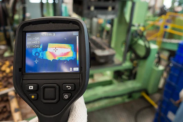
Table of content Introduction Evolution of Vision-Based Inspection Benefits of Vision-Based Inspection in Manufacturing Applications of Vision-Based Inspection in Manufacturing Challenges and Considerations Overcoming Resistance to Automation The Future of Manufacturing and Vision-Based Inspection Conclusion Introduction Quality control is essential in the quick-paced manufacturing industry for maintaining product uniformity and customer satisfaction. In the past, human inspectors have been used to find flaws and guarantee product integrity. On the other hand, a vision-based inspection system has become a game-changer in the manufacturing sector due to the development of modern technology. These systems are revolutionising quality control by improving accuracy, efficiency, and productivity using artificial intelligence (AI) and machine vision. The future of manufacturing is examined in this article, focusing on the importance of enterprises adopting automation. Evolution of Vision-Based Inspection Improvements have greatly influenced the development of vision-based inspection in processing power, AI algorithms, and high-resolution cameras. These systems were first restricted to basic operations like barcode reading and presence detection. Benefits of Vision-Based Inspection in Manufacturing KBE systems depend heavily on artificial intelligence, especially machine learning, which enables them to learn from data, spot patterns, and make wise decisions. Here are a few ways that AI and machine learning, through KBE, are revolutionising engineering design: Human inspectors are prone to mistakes and weariness, resulting in inconsistent fault identification and upholding quality standards. Conversely, vision-based inspection technologies provide unmatched accuracy and consistency in spotting even the smallest discrepancies. These systems are trained to identify particular patterns, characteristics, or flaws, ensuring the inspection process is impartial and trustworthy. Human inspectors’ time-consuming and repetitive responsibilities are eliminated by automation using vision-based inspection. The devices can fast process Large volumes of products, and instantaneous inspection findings can be obtained. This higher productivity, shortened lead times, and eventually cost savings for manufacturers result from increased speed and efficiency. By requiring less labour, vision-based inspection solutions assist with the expenses associated with manual inspections. Additionally, they make it possible for producers to find and fix problems at an earlier production stage by enabling early defect identification. These methods reduce scrap, rework, and customer returns, which cuts waste and improves overall operating efficiency. Applications of Vision-Based Inspection in Manufacturing Utilise Knowledge-Based Engineering (KBE)’s (amazing) AI capabilities to accelerate your engineering design process. Bid adieu to manual labour and welcome greater productivity, exactitude, cost savings, and a spurt of invention. Let’s explore the fascinating advantages that AI offers KBE: AI systems can precisely analyse massive amounts of data, which lowers the likelihood of human error. This reduces the possibility of expensive design faults and results in more detailed designs. Vision-based inspection systems can validate proper component alignment and positioning in intricate manufacturing lines. To ensure exact assembly and lower the possibility of defective or out- of-place items, they can compare acquired photos against predetermined templates. Early detection of faults allows producers to avoid problems later on and enhance overall product quality. Alphanumeric characters like serial numbers, labels, or codes can be read and verified using vision-based inspection systems with OCR capabilities. This technology makes Effective traceability possible throughout the supply chain and industrial processes. OCR-based inspections improve regulatory compliance, eliminate counterfeiting, and ease inventory management. Challenges and Considerations Although vision-based inspection systems have several benefits for production, they are difficult to implement. To achieve successful integration and ideal results, these elements must be addressed. Let’s examine the difficulties and vital elements to consider while implementing vision-based manufacturing inspection. Careful integration with the current manufacturing processes is necessary before using vision-based inspection systems. Compatibility with communication protocols, software, and hardware must be considered to ensure smooth operation. Manufacturers must choose simple solutions to incorporate into their current infrastructure and carefully plan the deployment process. Vision-based inspection systems generate Massive volumes of data from photos and videos. This data must be managed and analysed effectively for meaningful insights to be obtained and production processes optimised. Manufacturers should invest significantly in reliable data management systems and use data analytics technologies to extract useful information from inspection data. Vision-based inspection systems need frequent maintenance and training to operate at their best. A wide variety of product samples and defect types must be used to train the AI algorithms to identify and classify defects accurately. Additionally, producers must set up maintenance procedures to guarantee the systems’ dependability and endurance. Overcoming Resistance to Automation Although there is no denying the advantages of vision-based inspection systems, some manufacturers could be reluctant to adopt automation due to worries about job loss and up-front expenditures. It is crucial to understand that automation does not always imply the replacement of human labour. Instead, it enables them to concentrate on higher-value duties like inspecting inspection data, streamlining processes, and enhancing quality. Furthermore, long-term cost savings and increased productivity can benefit more than the initial investment in vision-based inspection equipment. When weighing the deployment of these technologies, manufacturers should consider the return on investment (ROI) and potential competitive advantages. The Future of Manufacturing and Vision-Based Inspection Automation is the key to the success of manufacturing in the future, and vision-based inspection is leading this change. These systems will grow more potent, precise, and adaptable as technology develops. The effectiveness and capacities of vision-based inspection in manufacturing will be further improved by integration with other developing technologies, including robotics, the Internet of Things (IoT), and augmented reality. Vision-based inspection technologies will maintain product quality and reduce environmental impact as the industry prioritises sustainability and waste reduction. Manufacturers may reduce waste and help create a more sustainable manufacturing ecosystem by identifying problems early in production. Conclusion The manufacturing sector is changing because vision-based inspection systems offer precise, effective, and reasonably priced quality control solutions. By embracing automation, manufacturers can obtain greater precision, increased efficiency, and lower costs. By utilising AI and machine vision technologies, businesses can streamline processes, enhance product quality, and gain a competitive edge in the global market. Ready to revolutionise your manufacturing processes with the vision-based inspection? Contact Prescient today to unlock the power of automation, accuracy, and efficiency in quality control.
Read MoreNeutral 3D CAD File Formats
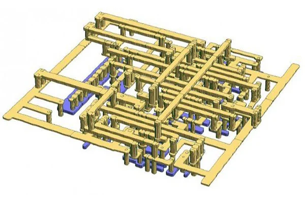
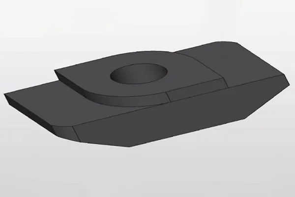
Table of Content Features of 3D CAD file formats Different 3D CAD File Formats Various CAD file formats have been developed in recent years. If you’re seeking the most suitable 3D model file, you need to know about the different file formats available. There are many benefits and drawbacks to each format, and you should know which one is right for your needs. Upon completion, every CAD design/model is saved in a respective file format. A 3D file format stores information about 3D models in plain text or binary data. The 3D formats encode a model’s following characteristics: However, not every 3D CAD format stores each of the data mentioned above. Each software comes with its specific 3D file formats. The variety in CAD file formats pertains to many reasons such as cost, feature, etc. It is necessary for any two software to enable interchangeability/interoperability to make things work. Before we talk about that, let’s take a quick walk through the evolution of CAD file formats. Features of 3D CAD file formats Everything comes with its variety, and CAD modeling is no stranger. As the technology evolved, CAD modeling came up in different styles and formats. Three-dimensional model files are often stored in one of two formats: Native (.dwg) or Neutral (.dxf). Native files contain the most detail, while Neutral files skip elements and contain only a basic representation. While there are many CAD Neutral file formats, not all of them are created equal. Some file formats have exceptional capabilities or features, while others are less compatible. Some formats are standardized, while others are proprietary. Considering there are different file types, they will come with specific properties. Other file types allow CAD model viewing in different ways. Some CAD files are limited to only 2D viewing to show the end customer. But since we are talking about 3D CAD models, the following are the main features of 3D CAD file formats: Native or Neutral The two main types of file formats are – Native and Neutral. Native 3D CAD file formats: All CAD design software uses a proprietary file type. Native formats are those that are native to a specific CAD system. Generally, such file types can only be viewed using the same software it was created with. However, it won’t open in a completely different design program. Proprietary files could be used in intercompany tasks. By using native file formats, designers can ensure that their chosen components are compatible with their PLM software. Native files contain the most detailed representation of 3D CAD models. Some notable native 3D CAD file formats are AutoCAD, Parasolid, Inventor, NX, CATIA, Solidworks, etc. Neutral 3D CAD file formats: Neutral 3D CAD file formats are those that are not proprietary to a specific program or file format. These file formats are useful in transferring 3D data from one program to another but do not contain as much fine detail as native CAD files. Neutral files skip elements and include only a basic representation. Neutral CAD file formats ignore the elements that are unnecessary for the software to create the design. Since they are interoperable, they can be viewed on many programs. They are helpful for engineers and designers who need to communicate with other departments and share a single design. Moreover, Neutral formats are not as compatible with all 3D CAD software, and many users do not have the time or budget to learn each one. Neutral data come in handy if the document is distributed to end-users who don’t use CAD software. Precise or tessellated CAD designs are displayed in two ways, namely, precise or tessellated. The difference lies in the fact that the product viewed while designing looks quite different from the actual product in real life. It is particularly noticeable in the case of lines and edges that form the product shape. This differentiates between precise drawings versus tessellated drawings. CAD software uses precise lines and angles to complete complex manufacturing processes to create a product. Such specific instructions must be included in a file format to edit the actual drawing or change its design. The lines and edges are tessellated while displaying a CAD drawing for visual purposes. Type of assembly Multi-part designs present a complicated situation when choosing a file format. Depending on the type of file format, multi-part product design may be limited to one single file for the whole assembly. Alternatively, designers also opt for separate files for each component. Awareness of how a particular software will display a multi-part product or if it will display a multi-part product is essential. Parts Listings CAD designs generally come with a list of parts. Different formats have different ways of presenting this part list. Some file formats have a Bill of Materials (BOM), while others, called Flat Lists, show all parts one by one. A bill of material showcases a single part and all its positions in a drawing. The latter is better for presenting all parts of an assembly. Different 3D CAD File Formats If you plan on using the same tool for several different projects, make sure the CAD tool you’re using is compatible with the standardized formats. Otherwise, you could run into problems. Popular CAD file formats include DXF, DWF, STEP, and Solidworks. Neutral file formats are widely used nowadays as intermediate formats for converting between two proprietary formats to counter interoperability. Naturally, these two known examples of Neutral formats are STL (with a .STL extension) and COLLADA (with a .DAE extension). They are used to share models across CAD software. Neutral 3D CAD File Formats STL: STL, which stands for stereolithography, is the universal format for pure 3D information. It is used in 3D printers and is somewhat loved by CAM. STL denotes only the surface geometry of a 3D object without any representation of color, texture, or other common CAD model attributes. It is a common 3D printer file format. To optimize the file for 3D printing, you can use export settings and the Polygon Reduction tool. A stereolithography file format created by 3D Systems stores
Read MoreWhat are BREP and CSG | Difference between BREP and CSG
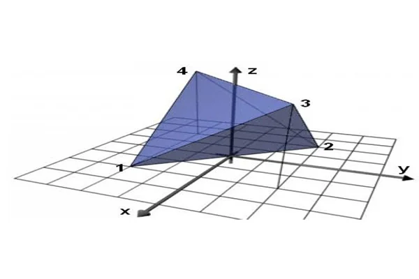
Table of Content Constructive Solid Geometry Boundary Representation Differences between BREP and CSG The geometric modeling technique has revolutionized the design and manufacture of products to a great extent. Although there have been various ways of representing an object, the most commonly used modeling technique is Solid Modelling. Boundary Representation modeling and Constructive Solid Geometry modeling are the two main ways to express solid models. Constructive Solid Geometry Constructive solid geometry or C-REP/CREP, previously known as computational binary solid geometry, is a reliable modeling technique that allows the creation of a complex object from simple primitives using Boolean operations. It is based on the fundamental that a physical object can be divided into a set of primitives or basic elements combined in a particular order by following a set of rules (Boolean operations) to create an object. Typically, they are objects of simple shapes such as cuboids, cylinders, prisms, pyramids, spheres, and cones. CSG cannot represent fillets, chamfers, and other context-based features. The primitives are considered valid CSG models, where each primitive is bounded by orientable surfaces (Half-spaces). These simple primitives are in generic form and must be confirmed by the user to be used in the design. The primitive may require scaling, translation, and rotation transformations to be assigned a coveted position. There are two kinds of CSG schemes: Primitive-based CSG: A popular CSG scheme based on bounded solid primitives, R-sets.Half-space-based CSG: This CSG scheme uses unbounded Half-spaces. Bounded solid primitives and their boundaries are considered composite half-spaces and the surfaces of the component half- spaces, respectively. Some attributes of CSG are as follows: Boundary Representation In solid modeling and computer-aided design, boundary representation or B-rep / BREP—is the process of representing shapes using the limits. Here a solid is described as a collection of connected surface elements. BREP was one of the first computer-generated representations to represent three- dimensional objects. BREP defines an object by its spatial boundaries. It details the points, edges, and surfaces of a volume. BREP can also be explained in terms of cell domain combination. A cell is a connected limitation of the underlying geometry. There are four kinds of cells as per the spatial dimension they inhabit: A domain is a set of connected cells grouped to define boundaries. Fields define various components inside a non-manifold object.Boundary representation of models consists of two kinds of information:Topology: The main topological entities are faces, edges, and vertices.Geometry: The main geometrical entities are surfaces, curves, and points. The topological and geometrical entities are intertwined in a way where: BREP comes with its share of advantages and disadvantages, which are: Differences between BREP and CSG Boundary Representation(BREP) Constructive Solid Geometry(CSG) BREP describes only the oriented surface of a solid as a data structure composed of vertices, edges, and faces. A solid is represented as a Boolean expression of primitive solid objects of a simpler structure. A BREP object is easily rendered on a graphic display system. A CSG object is always valid because its surface is closed and orientable and encloses a volume, provided the primitives are authentic in it. Basic operations include reviewing the possible surface types, the winged-edge representation schema, and the Euler operators for BREP. Basic operations include classifying points, curves, and surfaces concerning a solid, detecting redundancies in the representation, and approximating CSG objects systematically.
Read MoreFaceted Modeling and NURBS
Modern CAD systems and CAD packages enable designers to model objects and retrieve them in their formats. Some formats are interchangeable while some enforce restrictions, upon which, it becomes difficult to transfer an object model from one form to another. This article describes some of the most used CAD formats in the industry. But before we look into various CAD formats, it is essential to understand the concept of Faceted geometry and Analytic geometry (NURBS). FACETED GEOMETRY Faceted geometry, also known as discrete geometry, are models which consist of groups of polygons which is often triangles. Most Computer-Aided Design (CAD) systems typically use continuous surface and edge definitions based on NURBS. CAE simulations break down this NURBS representation into facets by a process known as meshing. The faceted models are quite appealing to engineering marketing, as such simulations are less bothered with exact physical reality and tend to emphasize on creating eye-catching visuals, such as airflow over a car, which can be incorporated into a marketing brochure. File formats typically used for faceted models are: .3ds, .dxf, .obj, .stl (Stereolithography). Almost all the faceted formats, except for STL, reflect material properties such as glass and metal by providing groupings of facets. However, such groupings are inadequate for a CAE simulation. ANALYTIC GEOMETRY (NURBS) NURBS or Non-uniform rational basis spline describes curves and surfaces with mathematical functions, and form the most common analytic geometry representations. The NURBS geometry has unlimited resolution. The NURBS definition defines the location of the boundary points and uses control points with slope definition to determine the internal shape of curves and surfaces, thereby enabling a great deal of flexibility. NURBS geometry is typically produced in CAD systems such as CATIA, Pro/Engineer, Solidworks, NX, etc. A significant drawback of NURBS geometry is that they are generally specific to the CAD packages that created them, and interchanging formats can be error-prone and inaccurate. DIFFERENCE BETWEEN FACETED GEOMETRY AND ANALYTIC GEOMETRY (NURBS) Faceted geometry NURBS geometry Facets are always guaranteed to comply with the original definition In NURBS geometry, different levels of model detail are created without losing fidelity Faceted geometry describes a shape as a mesh, points usually connected by triangles Analytic geometry defines curves and surfaces with mathematical functions Faceted geometry has limited resolution NURBS geometry has unlimited resolution Evaluating a faceted surface, one can get a shape defined by linear interpolation between known discrete points One can assess a NURBS surface anywhere and get coordinates lying on the surface Simple definition Includes topology Cons of Faceted geometry Cons of NURBS geometry Fixed resolution More computing intense No topology High data exchange Although faceted geometry has its use, NURBS geometry is superior for design and manufacturing processes. Due to the high demands on geometric precision, NURBS geometry finds its place in CAE applications. But if the modeling requirements ask for stunning visuals, faceted models are worth giving a try.
Read MoreTypes of Geometric Modeling
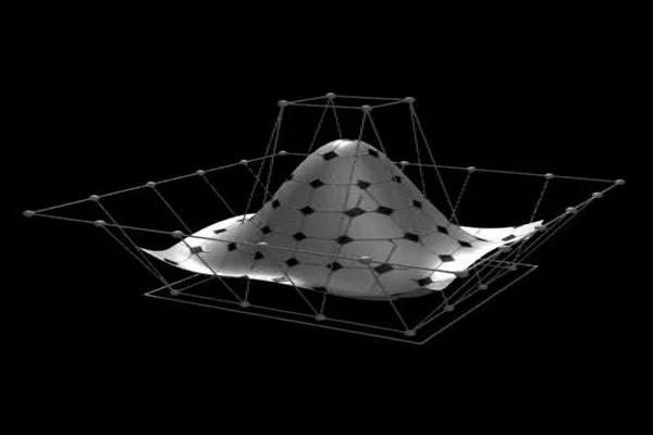
Table of Content Solid Modeling Surface Modeling Wireframe Modeling The previous edition gave a brief introduction to Geometric Modeling and its features. Geometric modeling is the mathematical representation of an object’s geometry. It incorporates the use of curves to create models. It can be viewed either in 2D or 3D perspective. The general design is applied to different geometric structures, including sets and graphs. This article introduces geometric models which represent geometric objects and their properties mathematically. They can be viewed as collections of squares of different colors. On the other hand, geometric shapes can be considered mathematical equations. Geometric models can represent data in context, such as a digital image. Regardless of the modeling approach, all students should understand how CAD software works. A basic understanding of geometric modeling is essential for any aspiring designer. In contrast, button- push robots often neglect this aspect of CAD training. However, preparing students with the fundamental knowledge of geometric modeling is also critical for their competitive edge. This edition details the primary types of geometric modeling. Geometric modeling can be classified into the following: Solid Modeling Also known as volume modeling, this is the most widely used method, providing a complete description of solid modeling. Solid modeling defines an object by its nodes, edges, and surfaces; therefore, it gives a perfect and explicit mathematical representation of a precisely enclosed and filled volume. Solid modeling requires topology rules to guarantee that all covers are stitched together correctly. This geometry modeling procedure is based upon the “Half-Space” concept. A solid model begins with a solid, which is then stitched together using topology rules. Solid modeling has many benefits, including improved visualization and functional automation. CAD software can quickly calculate the actual geometry of complex shapes. A cube, for example, has six faces, a radius of 8.4 mm, and many radii. It has many angles and a shallow pyramid on each face. By applying solid modeling concepts, CAD programs can quickly calculate these attributes for a given cube. Similarly, a cube with rounded edges has many radii and faces. There are two prevalent ways of representing solid models:Constructive solid geometry: Constructive solid geometry combines primary solid objects (prism, cylinder, cone, sphere, etc.). These shapes are either added or deleted to form the final solid shape.Boundary representation: In boundary representation, an object’s definition is determined by its spatial boundaries. It describes the points, edges, and surfaces of a volume and issues the command to rotate and sweep bind facets into a third-dimensional solid. The union of these surfaces enables the formation of a surface that explicitly encloses a volume. Solid Modeling is the most widely used geometric modeling in three dimensions, and it serves the following purpose: Different solid modeling techniques are as follows: Surface Modeling Surface modeling represents the solid appearing object. Although it is a more complicated representation method than wireframe modeling, it is not as refined as solid modeling. Although surface and solid models look identical, the former cannot be sliced open the way solid models can be. This model makes use of B-splines and Bezier for controlling curves. When polygons or NURBS represent surfaces, the computer can convert the commands into mathematical models. These models are saved in files and can be opened for editing and analysis at any time. The process of importing models from other programs is often complex and problematic, resulting in ambiguous results. In contrast, surface modeling allows for precise changes to difficult surfaces. A typical surface modeling process involves the following steps: Surface modeling is used to: Geometric surface modeling has proven to be extremely useful in computer graphics. Multiresolution modeling involves the generation of various surfaces at different levels of detail and accuracy. The resulting surfaces are then applied to various problems, including general surface estimation from structured and unstructured data. One such application is a subdivision surface, which begins from a simple primitive and gradually adds tools and details. Wireframe Modeling A wireframe model is composed of points, lines, curves, and surfaces connected by point coordinates. Because the model is not solid, it is difficult to visualize, but it helps generate simple geometric shapes. The resulting model contains information on every object’s point, edge, face, and vertices. This model is beneficial for creating an orthographic isometric or perspective view. The lines within a wireframe connect to create polygons, such as triangles and rectangles, representing three-dimensional shapes when bound together. The outcome may range from a cube to a complex three-dimensional scene with people and objects. The number of polygons within a model indicates how detailed the wireframe 3D model is. Wireframe modeling helps in matching a 3D drawing model to its reference. Planar objects can be moved to a 3D location once they have been created. It allows the creator to match the vertex points to align with the desired reference and see the reference through the model. Although Wireframe modeling is a quick and easy way to demonstrate concepts, creating a fully detailed, precisely constructed model for an idea can be highly time-consuming. If it does not match what was visualized for the project, all that time and effort is wasted. In wireframe modeling, one can skip the detailed work and present a very skeletal framework that is simple to create and apprehensible to others. Using a wireframe model as a reference geometry will help you create a solid or surface model that follows a definite shape. In this way, you can easily visualize your model and select objects. The wireframe model is decomposed into a series of simple wireframes and the desired face topology.
Read MoreWhat is Geometric Modeling
Table of Content Representation of Geometric Models Types of Geometric Modelings Requirements for Geometric Modeling The culture of design & manufacturing incorporates various crucial aspects for producing a market- efficient product. Computer-aided Engineering or CAE is a central part of the entire manufacturing process. Over the years, the function of CAE has evolved so much that it has developed its applications depending upon the type of usage and execution. Geometric Modeling happens to be one of the most popular CAE applications. Geometric Modeling is the computer/software-generated mathematical representation of an object’s geometry. It includes both graphical and non-graphical information. This information is stored in a database and displayed as a picture. It is then possible to edit and analyze the model in different ways. As curves are easy to manipulate and bend as per application, geometric modeling uses curves extensively to construct surfaces. The formation of curves can be achieved by – a set of points, analytic functions, or other curves/functions. The mathematical representation of an object can be displayed on a computer and used for the generation of drawings, which go on for analysis and eventual manufacturing of the object. In general, there are three conventional steps to creating a geometric model: Representation of Geometric Models There are two basic types of geometric models: a two-dimensional model, which is used for technical drawing, and a three-dimensional model, which is used for computer-aided design and manufacturing. Constructing a geometric model in CAD involves using a 3D computer program to describe geometric relationships and the physical extent of a component. The models may also contain material properties and other attributes of the element, such as the mass of the component. Many CAD programs can calculate a component’s mass properties and evaluate its other physical properties. These capabilities may be crucial for flexible and adaptive manufacturing lines. There are two main types of representations in geometric modeling. The classical presentation of geometric objects consists of geometric pointsets defined by boundaries. On the other hand, modern geometric modeling uses parametric families of pointsets. Parametric families are defined using geometric operation graphs, features, and constraints. In both cases, a user interacts with an example object from the family. It may also be a surface, a volume, or a solid. In addition to these models, geometric modeling can incorporate other design and manufacturing aspects. Computer- aided engineering, or CAE, is the central component of the manufacturing process. With the help of geometric modeling applications, key elements can be created, transformed, and integrated into the desired shape. In addition to this, CAD applications can also incorporate complex mathematical operations. Types of Geometric Modelings Depending upon the representations of objects, geometric modeling system can be classified into three categories, which are: Solid modelingSolid modeling also known as volume modeling, this is the most widely used method, providing a complete description of solid modeling. Solid modeling tools allow you to build many sides of an object at once. Solid models make multiple sides at once, reducing the ambiguity in surface modeling. Surface modelingSurface modeling is another popular method. This type of modeling represents the object by its surface and is used to describe the object with a clear view of manufacturing. This method uses surface geometry to create objects with complex forms. From this clear point of view, surface modeling cannot be used to develop an internal surface of any model. Surface modeling uses Bezier and B-spines. Surface modeling is better for design engineers as it organizes the edges that define polygonal surfaces. Wireframe modelingIt is a simple modeling system used to represent the object with the help of lines only. Hence, it is also known as Line model representation. However, wireframe modeling is not enough to express complex solids; therefore, it is used to describe only wiring systems. Wireframe geometric modeling is a good option for small-scale companies, where intricate surface details are essential for product design. Requirements for Geometric Modeling The various requirements of geometric modeling are as follows: Geometric modeling is a vast and elaborate field of CAE and requires in-depth study. The following articles dive deep into the various types and facets of geometric modeling.
Read MoreValue Engineering
During the lifecycle of a particular product, companies tend to review the existing design to look out for ways to reduce production cost. Even when coming up with a new product, so many manufacturers go for analyzing the same during its design phase so that it requires an optimum level of cost to produce. This is where Value Engineering comes in. Value engineering is an organized method to improve the “value” of a product or service in the lowest of cost. VE is a systematic approach aimed at obtaining the necessary functions in a product, process, or system at the minimum overall cost, thereby maintaining the quality, reliability, performance, and safety. It provides the substitution of materials and methods with less expensive alternatives, without jeopardizing the functionality. It is emphasized totally on the functions of various components and materials, rather than their physical characteristics. Value engineering is also called value analysis. It was Lawrence Miles who came up with the concept of finding substitute materials for parts unavailable. It was found that substitutions not only reduced cost but aided in a better-finished product. It was this new technique that evolved into value engineering today. The value in VE means two components: The function of a product is the specific task it was designed to perform, and the cost refers to the cost of the item during its life cycle. The ratio of function to cost denotes that the value of a product can be increased by either improving its function or decreasing its cost. In value engineering, the cost related to production, design, maintenance, and replacement are included in the analysis. If we take an example of a new tech product which is being designed and is slated to have a life cycle of only two years; the product will be designed with the least expensive materials and resources that will live up to the end of the product’s lifecycle, saving the manufacturer and the end-user money. This is how product value is improved by reducing costs. It is evident that with the increase in function value and decrease in price, the overall product value increases. Stages of Value Engineering There are three main stages to value engineering, which are: Benefits of Value Engineering Value engineering helps an organization in numerous ways: Value engineering concepts apply to business as well as technical situations and consequently lead management to informed, result-oriented decisions. Value engineering has to be treated as a future investment for gaining technology leadership in the industry.
Read MoreDesign Analysis – FEA, CFD, and Mold Flow Analysis
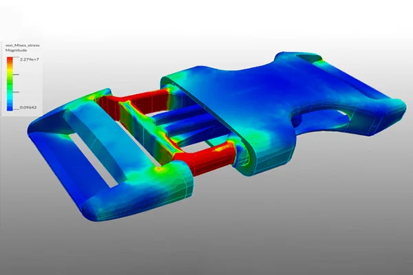
Table of content Finite Element Analysis (FEA) Computational Fluid Dynamics (CFD) Mold Flow Analysis Importance of CAE in design analysis Over the years, the term “Design Analysis” has been essential in the manufacturing sector. Instead of making a prototype and creating elaborate testing regimens to analyze the physical behavior of a product, engineers can evoke this information quickly and accurately on the computer. Design analysis is a specialized computer software technology designed to simulate the physical behavior of an object. If an object will break or deform or how it may react to heat are the sort of queries design analysis can answer. Design analysis helps in minimizing or even eliminating the need to build a physical prototype for testing. As a result, the technology has gone mainstream as a prized product development tool and found its presence in almost all engineering sectors. This article discusses three major design analysis software, namely: Finite Element Analysis (FEA) The Finite Element Analysis (FEA) is a specialized simulation of a physical entity using the numerical algorithm known as the Finite Element Method (FEM). It is used to reduce the number of physical prototypes and experiments and analyze objects in their design stage to develop better products faster. The term ‘finite’ denotes the limited, or finite, number of degrees of freedom used to model the behavior of each element. Mathematics is used to understand and quantify a physical phenomenon such as structural or fluid behavior, wave propagation, thermal transport, the growth of biological cells, etc. Most of these processes are described using Partial Differential Equations. Finite Element Analysis is one of the most prominent numerical techniques for a computer to solve these PEDs. FEA will analyze an object in question by breaking its entire geometry into small ‘elements,’ which are put under simulated conditions to see how the elements react. It displays the results as color- coded 3D images where red denotes an area of failure and blue indicates fields that maintain their integrity under the load applied. However, note down that FEA gives an approximate solution to the problem. FEA is used in problems where an analytical solution is not easily obtained, and mathematical expressions are required because of complex geometries, loadings, and material properties. Engineers also use FEA to reduce the number of physical prototypes, conduct failure investigations and improve component designs. It is also used by forensic engineers to determine stress concentrations in structures and to show alternative designs. Finite element analysis can help analyze fatigue-related failures. Finite element analysis has numerous other applications. Its advantages are many – it enables engineers to make better products faster. By breaking down a complex object into thousands or hundreds of thousands of finite elements, finite element analysis predicts how a given object will respond under a certain load. Furthermore, it helps forensic engineers confirm the stress concentrations in a case and show possible alternatives. FEA is also helpful for fatigue-related failure analysis. Computational Fluid Dynamics (CFD) Computational Fluid Dynamics (CFD) is a specialized simulation that analyzes fluid flows through an object using numerical solution methods. CFD incorporates applied mathematics, physics, and computing software to evaluate how a gas or liquid flows and how it affects an object as it flows past. CFD is based on Navier-Stokes equations which describe how a moving fluid’s velocity, temperature, pressure, and density are related. Aerodynamics and hydrodynamics are two engineering streams where CFD analyses are often used. Physical quantities such as lift and drag or field properties as pressures and velocities are computed using CFD. Fluid dynamics is connected with physical laws in the form of partial differential equations. Engineers transform these laws into algebraical equations and can efficiently solve these equations numerically. The CFD analysis reliability depends on the whole structure of the process. Determining proper numerical methods to develop a pathway through the solution is highly important. The software which conducts the analysis is one of the key elements in generating a sustainable product development process, as the number of physical prototypes can be reduced drastically. CFD is used in almost all industrial domains, such as: With the help of CFD, fluid flow can be analyzed faster in more detail at an earlier stage than by testing, at a lower cost and risk. CFD solves the fundamental equations governing fluid flow processes and provides information on essential flow characteristics such as pressure loss, flow distribution, and mixing rates. CFD injection molding is a widely used manufacturing process for plastic components. It has undergone many improvements over the past few decades, and numerical simulation models enable mold and part design without costly experiments. CFD has become an integral part of the engineering and design domains of prominent companies due to its ability to predict performance of new designs and intends to remain so. Mold Flow Analysis Moldflow, formerly known as C-mould, is one of the leading software used in processwide plastics solutions. Mold flow computes the injection molding process where plastic flows into a mold and analyzes the given mold design to check how the parts react to injection and ensure that the mold will be able to produce the strongest and uniform pieces. Using mold flow analysis, a manufacturer can reduce stress levels in its mold and increase filling and product quality. By assessing the flow of the plastic melt, Mold Flow can make informed design decisions and avoid costly mistakes. This software is an invaluable tool to improve quality and increase productivity. This software is beneficial for manufacturers that need to predict the flow of a mold and determine its feasibility. Two of the most popular mold flow analysis software are Moldflow and Moldex3D, used exclusively by many mold makers. There are three types of Mold flow analysis which are as follows: To simulate mold flow, a network of rectangular elements is discretized on the mold. The corresponding velocity field is then used to calculate the flow of the melt. A two-stage predictor- corrector method, developed by Hieber and Shen, has been used since then. Mold makers typically use the software
Read MoreGeometric Dimensioning and Tolerancing (GD&T)
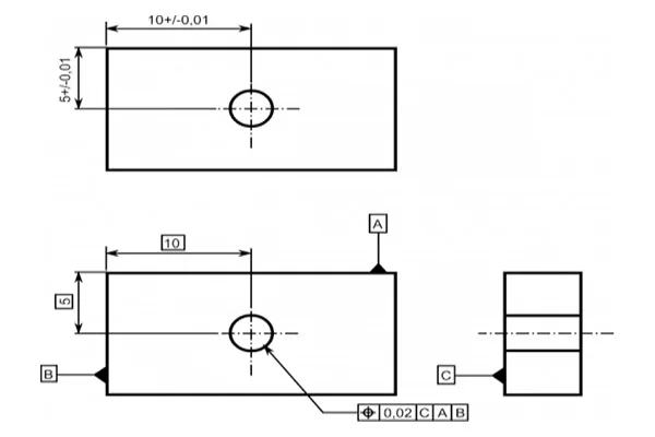
The design model is a depiction of a part design. However, the design model can never be an accurate representation of the product itself. Due to shortcomings in manufacturing and inspection processes, physical parts never match the design model exactly. An essential aspect of a design is to specify the lengths the part features may deviate from their theoretically accurate geometry. It is vital that the design intent and functionality of the part be communicated between the design engineers and the manufacturing unit. It is where the approach of GD&T comes into play. Geometric dimensioning and tolerancing or GD&T is a language of symbols and standards used on engineering drawings and models to determine the allowable deviation of feature geometry. GD&T consists of dimensions, tolerances, definitions, symbols, and rules that enable the design engineers to convey the design models appropriately. The manufacturing unit uses the language to understand the design intent. To master GD&T, one needs to understand the crucial concepts, which includes: GD&T is an efficient way to describe the dimensions and tolerances compared to traditional approximation tolerancing. The engineer might design a part with perfect geometry in CAD, but the produced part, more often than not, turns out to be not accurate. Proper use of GD&T improves quality and reduce time and cost of delivery by providing a common language for expressing design intent.
Read MoreWhat are DFMA and DFMEA
Table of content Design for Manufacturing and Assembly (DFMA) Design Failure Mode and Effect Analysis (DFMEA) During the last few decades, manufacturers have been able to source parts globally with the developments in technology. More and more manufacturers have entered the competition as it grows fierce. Companies in developing nation markets offer products at lower prices. To sustain business and achieve growth, many manufacturers are developing new products to cater to the consumers and widen it. They must be very marketable and of high quality. The Design for Manufacturing and Assembly (DFMA) method enables firms to develop quality products in lesser time and at lower production costs. Design for Manufacturing and Assembly (DFMA) Design for Manufacturing and Assembly or DFMA is a design process that targets ease of manufacturing and assembly efficiency. Simplifying the design of a product makes it possible to manufacture and assemble it in the minimum time and lower cost. DFMA approach has been used in the automotive and industrial sectors mainly. However, the process has been adopted in the construction domain as well. DFMA is a combination of two methodologies which are: DFM and DFA seek to reduce material and labor costs associated with designing and manufacturing a product. For a successful application of DFMA, the two activities should operate in unison to earn the most significant benefit. Through the DFMA approach, a company can prevent, detect, quantify, and eliminate waste and manufacturing inefficiency within a product design. Design Failure Mode and Effect Analysis (DFMEA) Design Failure Mode and Effect Analysis (DFMEA) is a systematic string of activities to identify and analyze potential systems, products, or process failures. Design Failure Mode and Effects Analysis or DFMEA focuses on finding potential design flaws and failures of components before they can significantly impact the end users of a product and the business distributing the product. The design failure mode and effect analysis – DFMEA is an ideal process for any sector where risk reduction and failure prevention are crucial, which includes: With expertise in advanced engineering, Prescient Technologies ensures maximum benefit to their client in terms of value addition, weight reduction, material selection, cost reduction, or manufacturing process selection. Visit our website for more details or send a message.
Read More